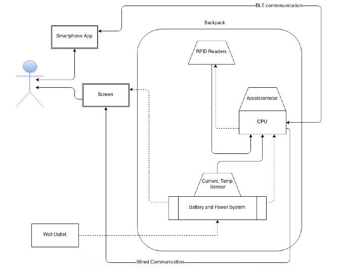
The diagram below depicts the high level architecture of our system. The RFID reading system draw its power from the processing system and sends information back to the processor about the tags that have been detected. The processing system (labeled CPU) also receives information from sensors such as the accelerometer and the current and temperature sensors that are placed near the battery. The processing system receives its power from the battery packs. The CPU then compiles the raw data that it receives and outputs it to the small screen that will be mounted to the straps (via wired serial connection, probably SPI or I2C). This screen will also be powered by the battery. A larger set of data will be sent to a smartphone (through BLE link), where the data will be compiled and displayed to the user in an app. This app will notify the user only in extreme cases, such as low battery or high temperature states.
All the dashed lines in the diagram represent power flow between devices, while the solid lines represent information flow.
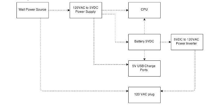
At a high level, whenever the backpack is plugged into the wall power will flow directly to the battery, 5V USB port, 120VAC plug, and to the CPU and associated systems. While it is unplugged power will flow from the battery to the 5V USB port, 120VAC plug, and to the CPU and associated systems.
The first battery of choice for testing is the EasyAcc battery. The battery will be charged using a 5VDC power supply, which will then be converted to a microUSB for charging the battery. The battery outputs 5V via 2 USB ports. These will be connected to a custom PCB that interfaces with the 5V USB port, 120VAC plug, and to the CPU and associated systems. This should be able to readily power the cpu as well as a charge port. The battery will also be connected to a 5VDC to 120VAC power inverter (a custom PCB). This will allow for the charging of a wide variety of devices.
Since we are using a 13.56 MHz RFID system, we should structure our system with RFID readers near the opening of the bag. Each item will need to be tagged and registered using the smartphone app. Then, when the item is brought close enough to the reader it will communicate the ID of its tag to the processing unit. The processing unit will then convey the ID to the smartphone over BLE, which will update its state.
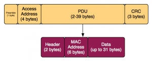
In an effort to minimize the power consumption from both the embedded controller and the smartphone, we use Bluetooth Low Energy as our communication medium. We use a Bluetooth 4.0 USB dongle attached to the Raspberry Pi. We format our Bluetooth packet to look like an iBeacon packet so that it can be easily picked up by applications, without requiring the application user to pair with the controller. Therefore, the controller will broadcast packets in the area for a certain amount of time. During this time, the smartphone application can receive and process the packets. The drawback to this model is that the controller in the backpack cannot receive responses from the smartphone.
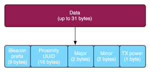
We use the 4 bytes in the Major and Minor data fields of the packet to store the information that we wish to exchange with the smartphone. Of these 4 bytes, the first is used as a flag to indicate whether the incoming packet is related to RFID data or to sensor data from the backpack (temperature). The remaining 3 bytes are used to convey specific data about the tag ID or the sensor reading (in Fahrenheit).