West Bond Wire Bonder
Description
The West Bond Wirebonder is for electrically connecting our MEMS chips to standard packages. We mainly use 40-pin DIP packages, but we also have workholders for TO-5 and TO-8 packages.
The bonder is currently set up to use 1 mil (25 um) gold wire through the 90-degree deep access wedge tool. It can also use 1 mil aluminum wire by switching the tool head to a 45-degree feed and clamp system. However, with the 45-degree clamp you won't be able to bond in tight corners of the package. For aluminum wire, the machine performs bonding by using the wedge to mash the wire against the device surface, while applying sideways ultrasonic vibration for a short amount of time. For gold wire, heat is also applied by a radiating coil around the wedge tool. Novice wirebonder users can use contact pads of 200 by 200 microns in die area, whereas more experienced users may push the threshold down to 150 by 150 microns or smaller. The size of the wire, when mashed down, determines the minimum bond size, and this is about 75-100 um.
Usage Policy
Several training sessions are required in order to use the wirebonder, which will last roughly an hour each.
The West Bond bonder has a memory for digitally storing recipes for various wire materials and package types. Most users will find "Au DIP" sufficient, however there are 40 spaces available, so you may store your own recipes if you like. You are encouraged to claim and name your own memory area if you need to make any changes to the basic recipes.
Contact
Name:
John Neumann
Office:
HH 1209
Extension:
x84404
Email:
jneumann@ece.cmu.edu
Qualified Users List
Name
Office
Extension
Email
John Neumann
HH 1209
x84404
jneumann@ece.cmu.edu
Brett Diamond
HH 1209
x84405
diamond@ece.cmu.edu
Prof. Ed
Schlesinger
Matte Zeleznik
maz2@andrew.cmu.edu
Shan Liu
shanl@andrew.cmu.edu
Standard Operating Procedures
The following gives you some idea what is involved with the operation of the bonder. This is far from a complete description, and you really need hands on training to understand it. You must get training from John Neumann before using the machine.
1) Register that you will be using the bonder on the sign-in sheet.
Follow the sequence in the text below as a guide:
PRELIMINARY Instructions for using the West Bond wire bonder, 17 October 2002
These instructions are not meant to be taken as permission to use the bonder without training. All users must meet with John Neumann (jneumann@ece) for training.
As of October 2002, we have a new wire bonder for the lab, a West Bond 4546-E79. It is similar to the old K&S wire bonder we had in that it does ultrasonic wedge bonding. However, the machine-human interface is very different, in that much of the movement of the wedge tool is automated. You can also do manual bonding, but my experience so far with the machine is that the automatic bonding is extremely accurate and easy to use, so I recommend this mode. The machine is also less likely to become unthreaded in automatic mode.
Users of the old machine will be delighted to learn that it doesn't need to be threaded very often. The main way the machine could come unthreaded is if the user moves the bonding tool backward and the wire comes out of the clamp. This is extremely unlikely in the fully automatic mode, and the wire feeding configuration of this machine also helps keep a stable path for the wire. Another way unthreading happens is if the wedge tool runs into an obstacle of some sort and the wire is knocked out of place. try not to do this because that can also damage the tool. If the tool does come unthreaded, please ask me for assistance, because threading this machine is quite tricky. The wire must come down a narrow tube on its way to the clamp. This is REALLY hard to thread and I don't want to repeat it. If the wire comes out of the wedge only, it is not as big a deal, being only slightly more difficult than the old machine to thread.
Here is the general sequence for operating the machine in fully automatic mode. It serves as a reminder of the steps to follow, assuming you've alrady been trained in person.
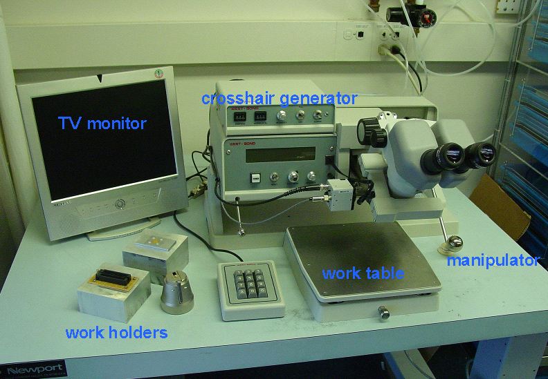
Turn on machine, crosshair generator, TV monitor
If you are using gold wire (that is how the machine is set up right now) turn the tool heat setting to 4.0 and wait a few minutes before bonding. Don't touch the metal coil around the wedge tool, because it will be very hot.
Position sample in the workholder under camera. Note that when you can see through the camera and monitor, the wedge is actually pulled back (away from operator). It will snap back under the camera (and block its view) under many circumstances, like when it's actually bonding.
SET WORK HEIGHT
edit menu (4)
machine settings (6)
restart ht (9)
work height (7)
It is best to do this so the work height is optimized for the chip surface, because then that will be in focus. Press "G" then wedge will come down (and won't stop in this mode- be ready to position landing spot). Follow instructions- turning knob clockwise raises work table. The machine will beep and the display will briefly read "Good" when you get there.
BOND-OFF/ALIGN CROSSHAIRS AT HEIGHT OF CRITICAL BOND
THREAD/BOND OFF menu (6)
You want to do this on your chip (the critical bond surface) because the position of the crosshairs in the camera is dependent on height because of parallax. press "0" to do it slowly, "G" to do it faster. After the bond is made, manipulator arm will lock in place, and then you take your time to set crosshairs on bond, and hit OK (G).
SET HEIGHTS, WIRE LENGTH
Next you will set the bond heights and the wire length. Before you do this, you need to make sure that the two bond targets are lined up in a straight line away from you. Do this by using the "7" key (LOCK/MOVE X) along with the manipulator handle to go back and forth while you adjust the angle of the workholder on the table. When you get the angle adjusted don't touch the workholder anymore.
Now you go to learn mode to set up the machine to make the bond:
EDIT menu (4)
LEARN MODE (G)
This will take you through a sequence of steps that set the search and loop heights, and the wire length. Generally, if you are using a recipe that is already tested for your chip and package, you will only need to make adjustments to the wire length ("Y offset"). But it can't hurt to go through the adjustments listed below, in case there are some variations in the package thickness or the chip thickness.
The first step that you will need to adjust is search height for bond #1. This is done by positioning over the 1st bond area (the instructions will lead you to this), and hitting SUGGEST (8). The wedge tool will come down, contact the surface, and pop back up to the appropriate height. The next few settings you can leave alone (Z-before-Y, backbend) or use suggest again. Use SUGGEST to choose a loop height. Unless you have an unusual height difference between bonds, whatever the machine suggests will be fine. Next step is to set the Y-offset (which is the length of your bond wire). Make sure the height of the wedge is above any surfaces so you don't hit the side of anything, and use 5 and/or 0 to move the wedge approximately above the bond pad. You will have a later opportunity to fine tune this position. Next few options will be search height #2 and something about the clamp. Use suggested value for the clamps. The search height adjustment is similar to bond #1. Position the wedge above the surface, and hit "8" for "SUGGEST". Then you will have a chance to set the final adjustment of Y-offset. You can also go back to "previous option" as many times as you want to get it right. When you are satisfied, continue through the options by pressing "G" and you eventually pop back to the home menu.
MAKE BOND
This is written assuming that your critical bond (the one you aim the crosshairs at) is bond 1, and you are bonding from the chip to the package. It is possible to choose bond #2 as your critical bond, and bond from the package to the chip. You might want to do this if you are bonding within a very high-walled package with pads close to the wall.
[Make sure if you are expecting the critical bond to be #2, that the display says "ALIGN BOND 2 OF 2". Sometimes there is a glitch in the software that resets it to 1 OF 2, and you don't want that. If that happens, see below. Otherwise, when you do the bond, the machine will start where you are expecting it to end, and end in some possibly bad place, like on your structures, smacking into the package wall and dethreading or damaging the tool.]
If the critical bond setting is not what you want, then edit the wire type:
EDIT (4)
WIRE TYPE (9)
CRITICAL BOND (7)
To make the bond, aim the crosshairs at the critical bond pad, and press "G" and wait until the bonder makes the bonds. You can see the result through the TV or microscope.
wire comes unthreaded from wedge: see John
make sure machine is in full/half automatic mode: More options (8)/ Toggle mode (8)
make sure there is enough tail (use FEED, then bond-off)
crosshairs drift from true target. Use bond-off occasionally to reposition. Camera mount may need to be tightened.
Many of the menu items may be hard to find. There is a complete map of the menu system on pages 30 and 31 of the West Bond manual.
critical bond: the bond on which it is more important to have precise placement of the bond. Usually the bond pads on your chip are much smaller than on the package, so for most cases this is the bond on the chip.
device: It is possible to store 40 different "recipes" in the bonder, and give them short names. I've created a few already, but some are for the aluminum wire settings. The settings for making the bonds (power, force, time, etc) are associated with each device. "Au DIP" should work for chips on the DIP packages we have around the lab, using gold wire.
You can copy devices into other locations and edit the copies if you're doing something new or unusual or if you just want your own device recipe. Go to EDIT (4)/DEVICE EDIT to copy from one location to another. You can create or edit the name by going into learn mode and going to one of the first few options.
bond edit: You probably shouldn't mess with this. I've programmed in settings that work well with our wire, packages, and chips.
wire type: This you can edit for the number of bonds per wire, and set which is the critical bond.
loop edit: Here you can edit the search and loop heights, as well as the Y-offset (length between 1st and 2nd bond). It is the same as "learn mode", I think, but you can access things randomly rather in sequence.
deep access wedge: Currently there is a 45 degree wedge installed, meaning the wire is fed from a clamp that sits at a slight angle behind the wedge. This works well with aluminum wire, but the clamp can run into the package walls if you are bonding close to the walls. In contrast, a deep access wedge has the wire feeding straight down, and the clamp is above the wedge. The plan is to put a deep access wedge on the machine very soon.