H.261 consists of three main parts: the encoder, the decoder, and the transport mechanism. As we have three group members, we have divided the work among the group in this fashion. Since the encoder itself uses the decoder in its feedback loop (to minimize error accumulation), the decoder was developed at the same time as the encoder.
First, fast versions of the relevant algorithms in H.261 were developed.
Motion estimation and compensation is the most time-consuming algorithm
in the system. An efficient DCT and inverse DCT for an 8x8 block were also
developed. The following subsections will discuss the fast algorithm implementations.
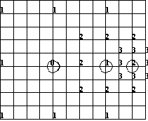
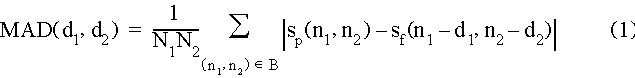
Look at the above figure where part of a block was shown. In the first step, the candidates are nine vectors corresponding to "1" and "0" points. Calculating motion estimation via eq.(1) and eq.(2). If "0" point is the estimated motion vector, stop searching. Otherwise, we begin the second step where the candidates are another eight points ("2") centered around the estimated vector (circled "1") in the first step. If the estimated vector is circled "1", stop searching. Otherwise, start the third step where the candidates are updated as eight "3" points centered around the estimated vector (circled "2") in the second step.
Compared to full search which would take 16x16=256 searches, three step procedure requires at most 9+8+8=25 searches. Although it may miss the optimum candidate, three step scheme speeds up the searching process by 10 times.
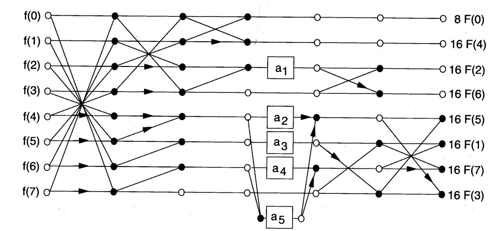
The inverse DCT can be implemented in a similar way by reversing the flowgraph of the corresponding forward DCT.
2. Encoder and Decoder
The encoder and decoder are design to receive a data stream and process it. The encoder receives QCIF YUV video frames and produces a "compressed" data stream. The decoder receives the "compressed" data stream and generates QCIF YUV video frames.
We constructed the main elements of the encoder and decoder during the efficient algorithm development stage. Only a few key decisions remained.
For videos containing fast moving objects, motion estimation may lead to large error residues. A decision between inter-block coding (using the motion estimation and a coded residue) and intra-block coding (using the uncompensated macroblock) is necessary. At this time, intra mode is preferred where coefficients of current frame instead of those of residue frame are transmitted. The choice between intra and inter modes is based on RM8. Motion estimation information can be saved if using intra mode.
The decoder takes the data streams from the entropy decoder and reconstructs
the video sequence. The decoder has two buffers: the input buffer holds
the input data associated with the current frame to be decoded; the output
buffer holds two frames, one for the previous frame that is used in motion
compensation and the other for the current frame as output. After one frame
has been decoded, the pointers to the previous frame and the current frame
are swapped and the current frame is sent to the display unit. The decoding
is done macroblock by macroblock. For each macroblock, header information
and block data are read from the input buffer. Depending on the encoding
mode of the macroblock which is specified in the header, the macroblock
is decoded in various INTRA or INTER mode. All of the ten coding mode can
be processed. The data of the six blocks in one macroblock is dequantized
first and a fast inverse DCT algorithm is implemented to reconstruct the
block data from the DCT coefficient. The decoder is also embedded into
the encoder as a part of motion prediction loop.
One machine has a 150 MHz Intel Pentium Pro and 64 MB of RAM; the other machine has a 66 MHz Intel 486/DX2 with 16 MB of RAM. A miroMedia PCTV PCI framegrabber card was used in the Pentium Pro machine, and a VideoLabs CCD camera (producing NTSC-quality video) was attached to the framegrabber.
X-Windows was run with 8 bits per pixel.
The Linux driver for the framegrabber was obtained from the BTTV homepage http://www.thp.Uni-Koeln.DE/~rjkm/linux/bttv.html
The driver supports two modes: a direct view mode, in which the framegrabber communicates over the PCI bus to a section of memory on the video card, and DMA mode, in which the framegrabber communicates with the main memory of the system. Direct view mode supports the fastest frame rates, as it interacts directly with the display device. The driver is responsible for maintaining the memory correctly. Under X-Windows, a direct mapping of the X display to the frame buffer is required.
The driver also came with a small program that used an explicit call to the card to obtain a frame of video. The driver exports this call through an IO control call (ioctl), and takes as an argument the memory to copy the frame into. The card can be configured to grab in a variety of modes; we chose 24 bpp RGB, as that was the default. The card will also scale the image in hardware to the required size, so we were able to directly obtain QCIF images (176 x 144 pixels).
A small section of code was written to convert the RGB data to YUV data, and to decimate the U and V planes by two in both X and Y so that 4:2:0 YUV frames were generated.
The code for interacting with the driver and converting the images was
placed into a C++ class call yuv_video. When a new frame was requested
with the Get_Y, Get_U, and Get_V methods, the driver
was invoked and the color conversion performed.
A small socket class was created to handle the communication between two pieces of software. The socket class supports one of two modes: "receive", which waits for communication on a specified network port, and then establishes a socket; and "send", which communicates with the "receiver".
The sockets were configured to use TCP/IP, which guarantees that all packets sent will be received properly. Another option, which is slightly faster, is to use UDP/IP, although the guarantee of proper reception is lost. Since the two machines share an Ethernet hub, using TCP/IP is roughly equivalent to UDP as there are few collisions and dropped packets (dropped packets cause TCP to resend the missing information).
To ease portability, the socket file descriptor was then used to create a buffer I/O stream (using the C++ fstream class). This allows for C++ file stream operators to use the socket like any other file, and allowed for easy testing: to convert the code from reading a disk file to reading a socket, only the "open" statement was changed.
The operating system then handles the generation of packets, transmission,
reception, and so forth. Our code just reads bytes or writes bytes to the
file stream.
By using 8-bit displays, we were guaranteed that a "pixel" was a single character, and could then directly map pixel values to R/G/B values through the color allocations.
A routine for color allocation and dithering was borrowed from the MPEG-2 decoder, available at ftp://ftp.cstv.to.cnr.it/pub/MPEG2/conformance-bitstreams/video/verifier/.
This decoder supports 8-bit displays and dithers by quantization of the Y/U/V space, allocating 4 bits to Y and 2 bits to U and V. The quantized value is then used to look up an allocated colormap entry.
The routines for display were also placed in the yuv_video class.
When a complete frame was written to the class using the Put_Y,
Put_U, and Put_V methods, the frame was dithered and displayed.
The code was instrumented to obtain timing measurements for different
aspects of the encoder and decoder. The encoder was measured for the motion
estimation algorithm time per frame (as well as the number of MAD values
calculated) and the total time to perform the DCTs and quantization stages
per frame. The decoder was instrumented for its entire time to decode the
frame, as it involved only inverse quantization, inverse DCT, and motion
compensation. The yuv_video class was instrumented for framegrab
time and frame display time.
| Code Measured | Description | Time |
| Read Video | FrameGrabber IO | 50.64 ms |
| Color Conversion | 8.9 ms | |
| Decimation | 2.5 ms | |
| Read Total | 61.5 ms | |
| Encoder | Motion Estimation | 207.85 ms |
| DCT, Quantization, Scan | 46.9 ms | |
| Encoder Total | 254.8 ms | |
| Decoder | IDCT, Inverse Quantize, etc. | 41.7 ms |
| Display | 18.25 ms | |
| Network | Write time | 443.1 ms |
| Write bandwidth | 2788.3 kbps | |
| Total | Total encoder + write time | 833 ms |
| Framerate | 1.2 fps |
Since the audio bandwidth in H.320 is of little concern running on 10 Mbps Ethernet, it has been suggested that we send raw audio data and not concern ourselves with compression or decompression. In that case, only synchronization of the audio stream with the video stream will be necessary.
The majority of the remaining work, therefore, is in the generation
of entropy-encoded bitstreams, bitstream management, and synchronization.
We have discovered several things while implementing this portion of our project.
(1) Project is not pure research and efficiency is vital. Although MAD and three step search may not give the optimum results, they are effective and reduce a lot of computation.
(2) Encoder and decoder should be developed in parallel or by one person. Some minor inconsistency between these two codes would arise a lot of problems during the stage of integration.
(3) We have learned the implementation of fast DCT and inverse DCT. FDCT can run five times faster than a conventional DCT. The performance of the decoder is greatly improved by using the fast DCT. We have fully understood the process of motion compensation in video compression.
(4) We now have an understanding of different color spaces, color dithering, and some idea about algorithms for manipulating image formats.
(5) We also have an understanding of some of the behaviors of hardware used in video systems.
(6) Finally, weve learned that group projects work best if there are
specific goals that can be reached. In addition, having a common working
environment is almost necessary, for issues in portability and development
environments can overwhelm the overall goals of the project.