Actuation
The drawing system will have a harnessed pen suspended from cables that is used to draw on the board. The cables will be attached to steppers at each corner module through a tensioning rod. These modules will be able to control the tension on the cable allowing them to move the harness. To extend and retract the pen, we will use a Sarrus linkage mechanism. Using a control loop we will be able to determine the exact amount of tension to keep on each cable in order to hold the pen steady at either a retracted or extended state.
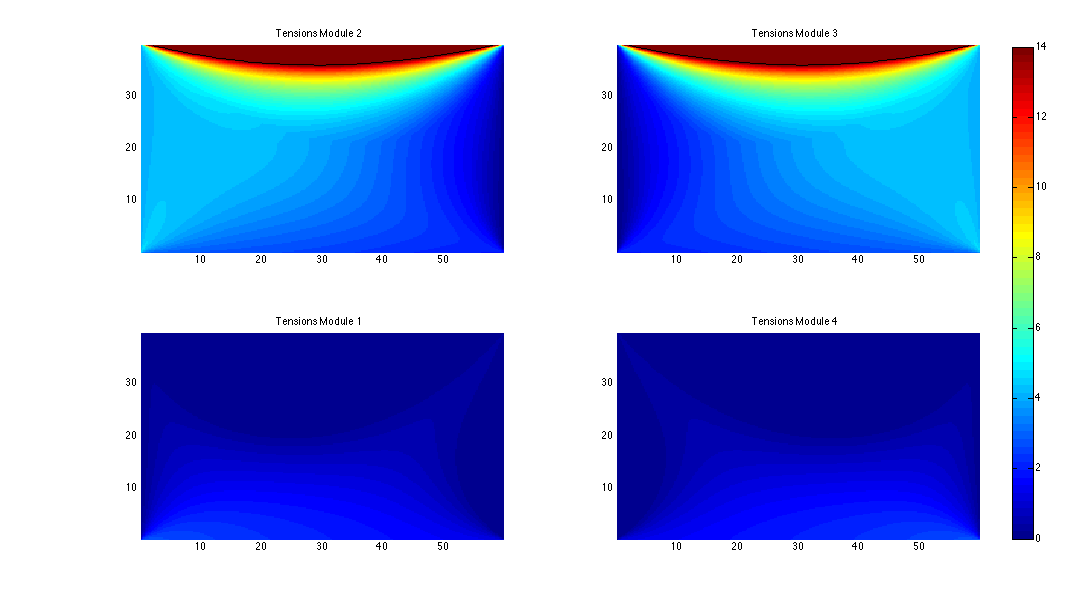
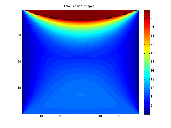
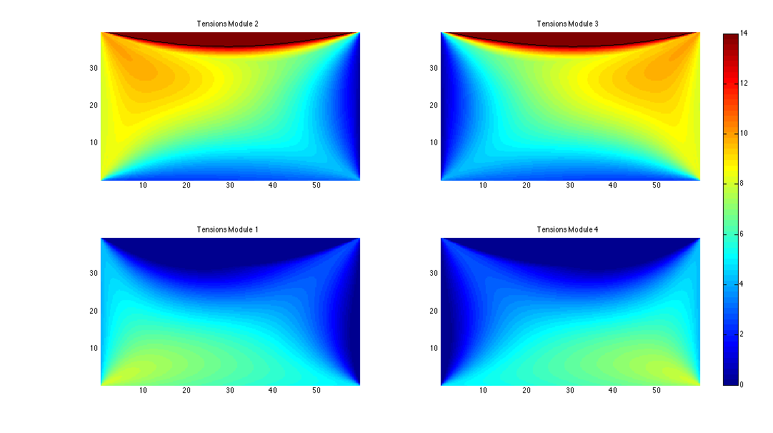
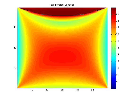
In a simulated system on a 60" by 40" whiteboard, we have determined the optimal cable tensions at each point in order to maintain an average 2oz and 6oz force per cable. On these charts we also place a contour line showing where the required force exceeds the maximum force available from the steppers. This reflects the possible working area on the board. The colorbar to the right of each image indicates the colors for the tensions in ounces.
2oz Module Tensions
2oz Total Tension
6oz Module Tensions
6oz Total Tension
In order to support movement, there are two approaches we will test: using a control loop to control the tension on each cable at each point in time; or, using a control loop to control the amount of cable let out at each point in time. While controlling the tension at each point in time may produce more accurate results, we will be limited by the acceleration profiles of our steppers. In the end, this may produce more unstable results. On the other hand, controlling the amount of cable let out at each module is very straightforward, however it may not give us as much control over where the harness is.
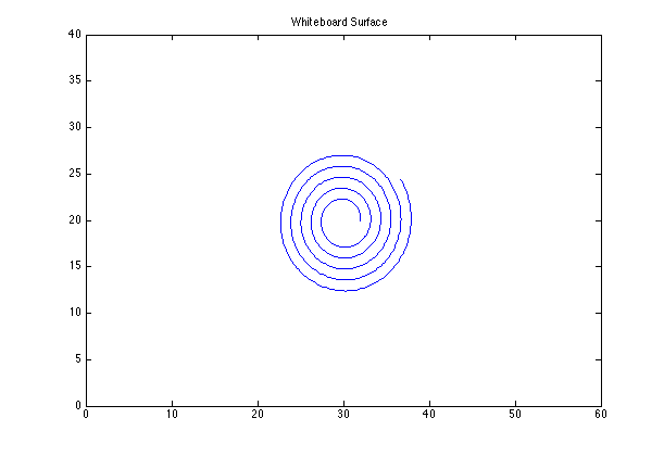
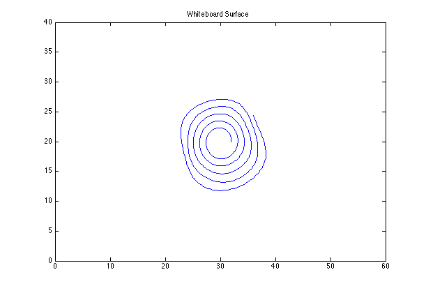
As a first step in determining which method to use, we have simulated each method in MATLAB and compared the results. Currently the model does not take into account maximum stepper speed, however this can be accounted for by a simple time dilation. Here are the results of drawing a spiral over 8 seconds:
Stable Spiral
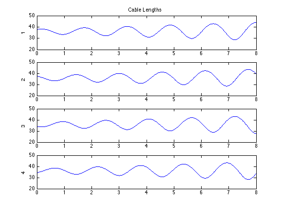
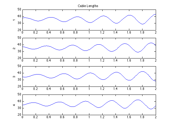
Stable Spiral Cable Lengths
Stable Spiral Cable Tensions
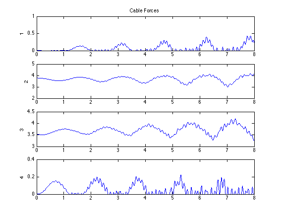
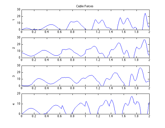
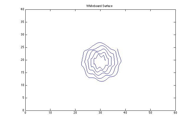
Notice how the tensions never exceed 5oz. In the model, the maximum cable tension that the steppers will maintain is 14oz. If we try to speed up the drawing of the spiral so that the required forces exceed 14oz, you can see that the drawing destabilizes due to the higher cable tensions:
Unstable Spiral
Unstable Spiral Cable Lengths
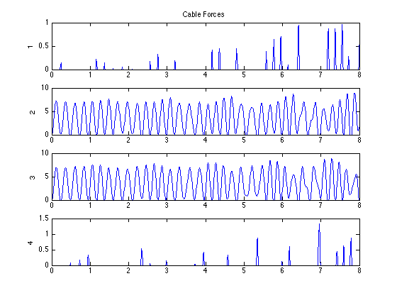
Unstable Spiral Cable Tensions
Both of these simulations worked by precomputing the optimal cable lengths that induce the correct force to produce the proper accelerations required to reach the desired position. Overall this is a fairly computation heavy process. An alternate (and naive) method would be to just let out the amount of cable equal to the desired distance of the harness from each module. We find that this produces significant oscillations due to not taking into account the tensioning springs:
Naive Spiral
Naive Spiral Cable Lengths

Naive Spiral Cable Tensions
In the end, our control loops do not entirely reflect these cases, as these cases work by entirely precomputing cable lengths while the control loop would be actively managing tension and position. However, should the control loop be unstable, the first method presented may be an effective alternative.