Enlighten.
Using light bulbs to transmit the world's data.
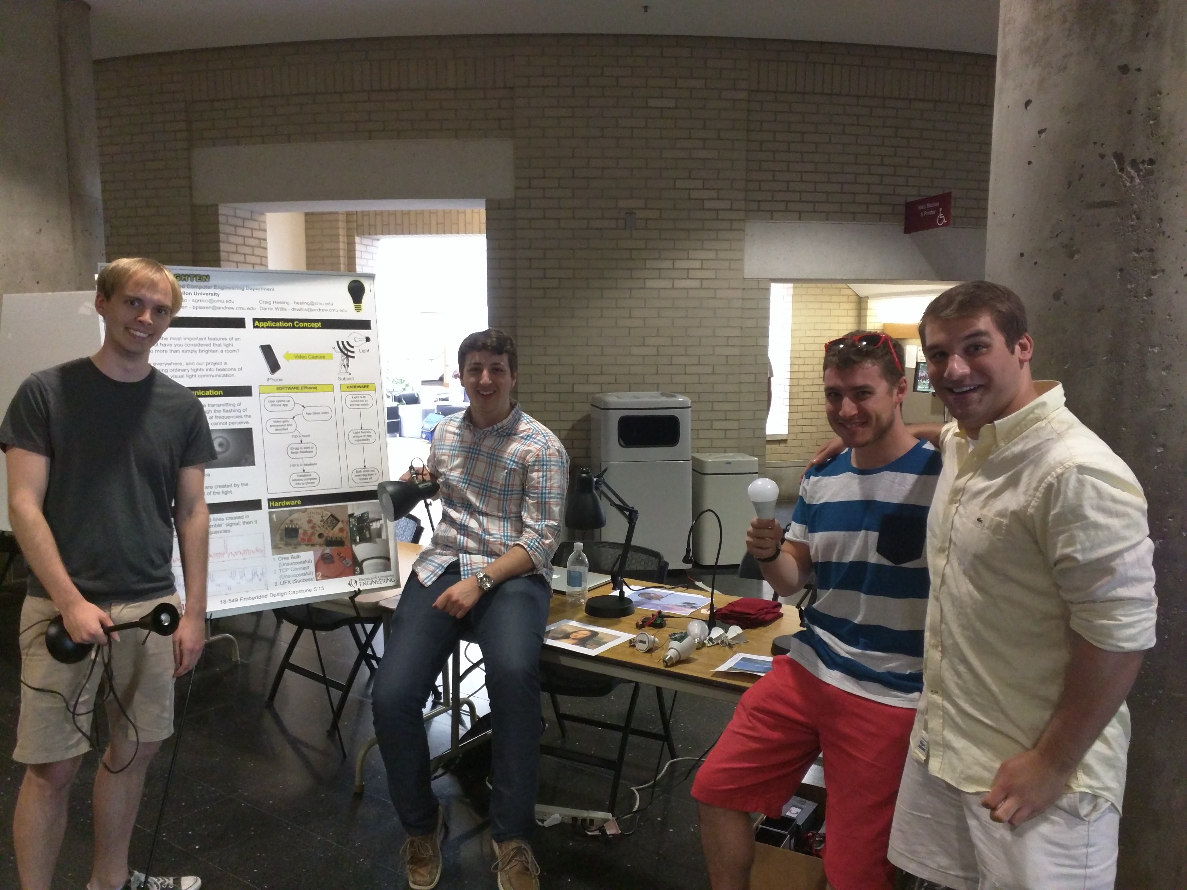
The Team

Project Concept
Lights are ubiquitous in indoor environments, and are an underutilized sensing resource. The goal for our project is to take advantage of a standard LED light bulb to transmit information that can be captured by a standard iPhone camera for location detection.
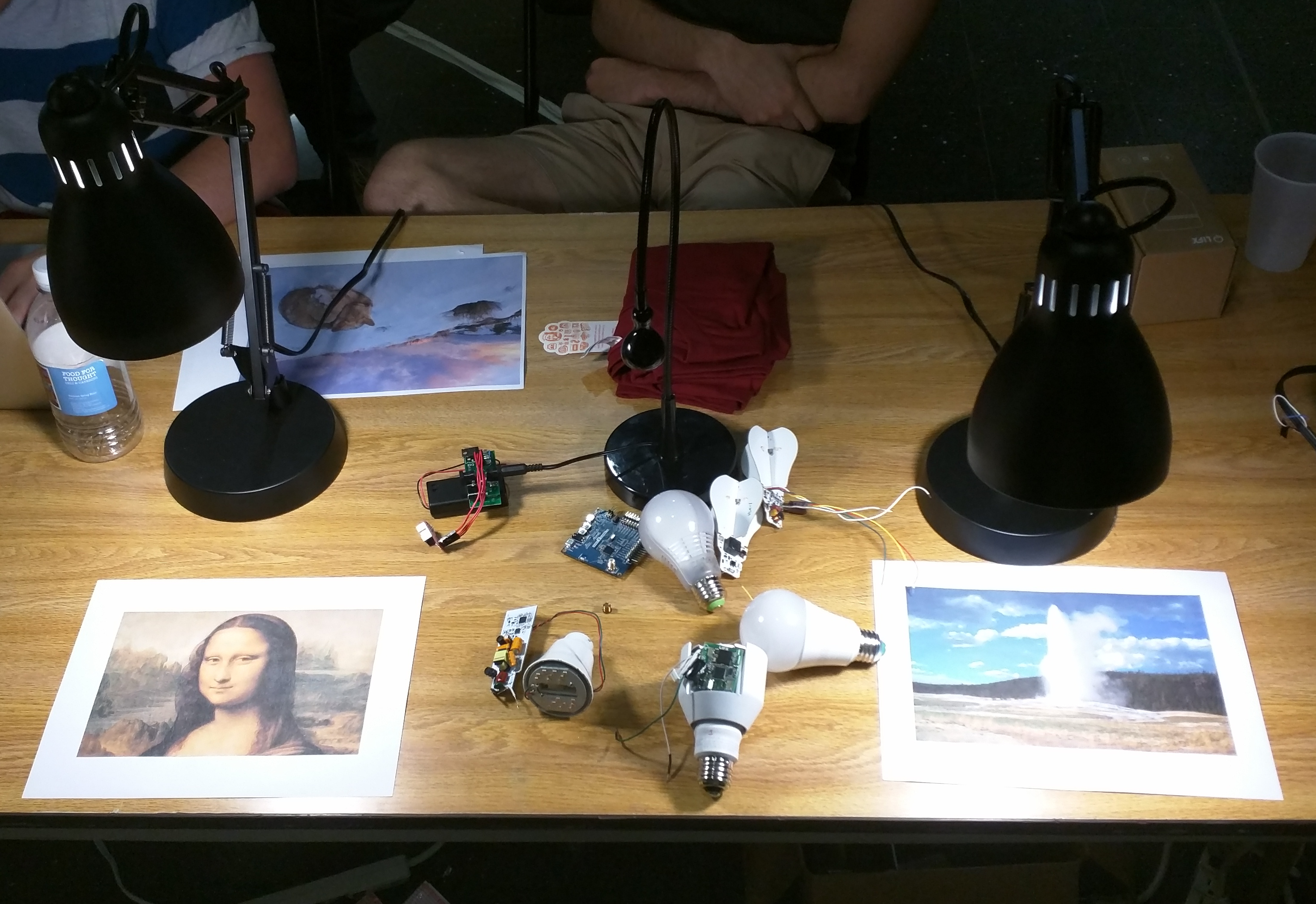
Photos
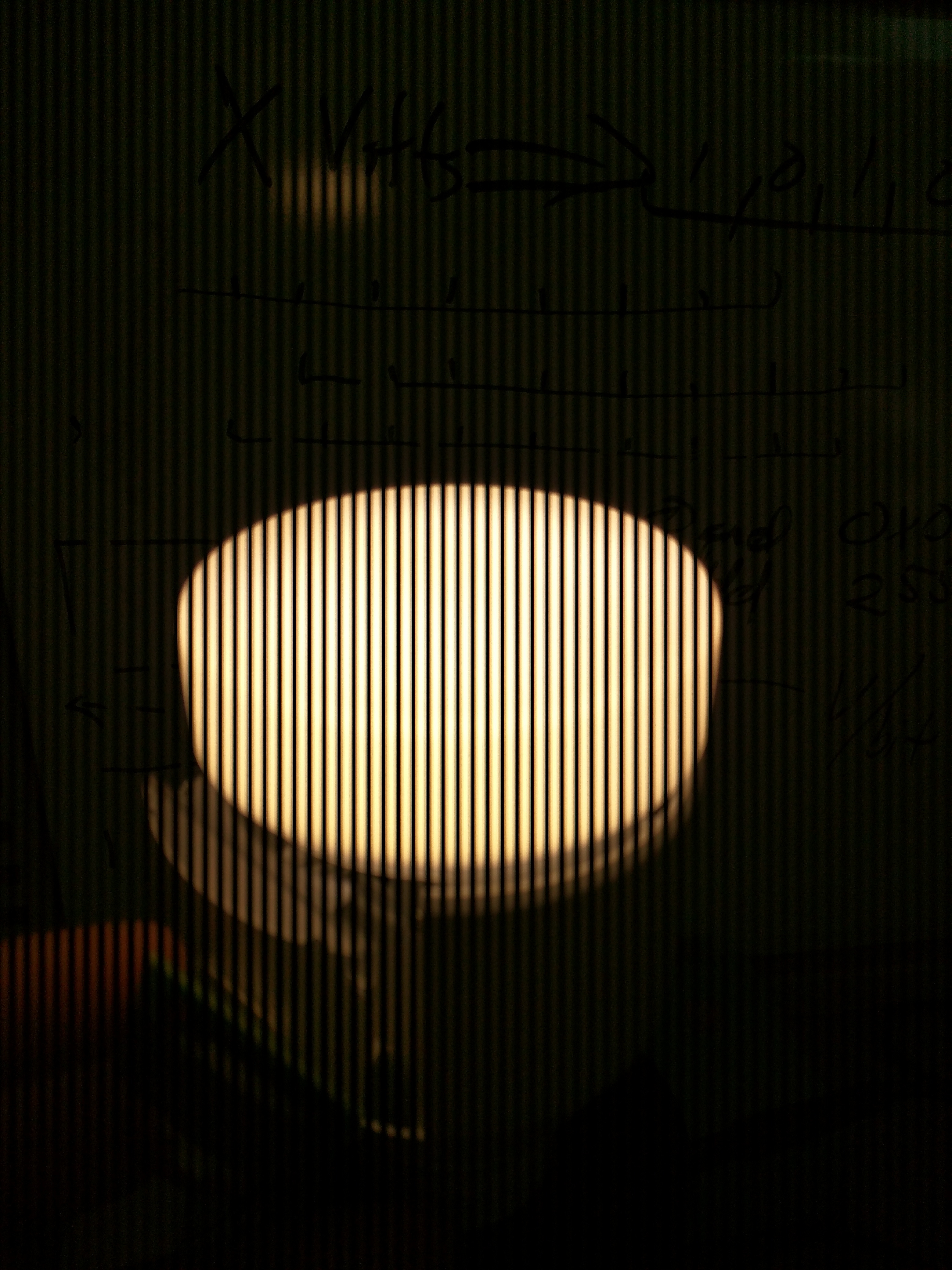
Motivation
There are currently a variety of methods of communicating wirelessly between devices; some examples include WiFi, Bluetooth, and cellular/LTE. Each of these forms of communication have a couple of things in common: they pass quite easily through solid walls, and they require antennae to transmit and receive the data. There are some situations in which having the signal not pass through walls is actually a huge benefit (a prime example being indoor location tracking). Using visual light as the medium for communication allows us to both eliminate the need for antennae, and allows us to transmit data in an isolated environment.
Competition
This project draws heavily from research inherited from work done by Niranjini Rajagopa, Patrick Lazik, and Anthony Rowe at Carnegie Mellon. This research group created a wired system using conventional boards and a custom microcontroller amplifier setup to transmit data using visual light communication (VLC).
In addition to the research done in VLC at Carnegie Mellon, our direct competition consists of other forms of short-range wireless communication, including but not limited to:
- Bluetooth® 4.0: The IEEE 802.15.1 wireless standard allows for the transmission of data across short distances while consuming very little energy. Our project differs from Bluetooth® in that we do not require a special antenna to transmit data, so the energy consumption on a receiving device should be theoretically lower. Also, our signal would be more localized, since unlike radio signals, visual light cannot travel through solid objects like a wall.
- ZigBee®: Utilizing the IEEE 802.15.4 standard physical layer, ZigBee® is intended to be simpler and less expensive than other short-range wireless networks. Although we intend to utilize an open-source implementation of ZigBee® to communicate between our bulbs, the advantage we offer is that our wireless signal will be compatible with smartphones, which do not normally come equipped with IEEE 802.15.4 standard antennae.
- Wi-Fi™: The most common WLAN implementation today, the IEEE 802.11 standard allows for the high-speed transfer of large amounts of data from multiple sources to a single hotspot. A traditional Wi-Fi antenna requires a lot of energy to both transmit and receive data, and all data must be routed through a hotspot in order to communicate between devices. The advantages we offer over this are that we can communicate directly with a device, plus our signals are more localized, whereas Wi-Fi signals can usually reach across an entire building.
Design Requirements (functional and non-functional)
Transmitter
- In order to take full advantage of the frequency spectrum the iPhone camera can pick up, our LED bulbs must be able to pulse at a minimum of frequency of 10kHz.
- The system should ideally fit into a commercial LED bulb, so it can be powered in traditional light sockets.
- We should be able to "hack" existing commercial bulbs without destroying them; to do this we plan on creating a special adapter that connects directly to the pins on a bulb's MCU.
- The bulbs we use should not produce any buzzing sound or noticeable flickering effect; the fact that we are transmitting data should be virtually unknown to anyone looking at the bulbs.
Receiver
- The iOS app should be able to utilize the full framerate of the iPhone camera such that we get the maximum reading of whatever signal is coming in.
- Image and signal processing should ideally happen in real time, with latency of at most a second or two.
- The app should be able to differentiate between multiple signals coming in at the same time (from multiple nearby bulbs).
Technical Specifications (for one bulb)
Please note: in the early stages of our project we are still experimenting with various components. Listed below are our current best picks for the various sections of the project.
Hardware
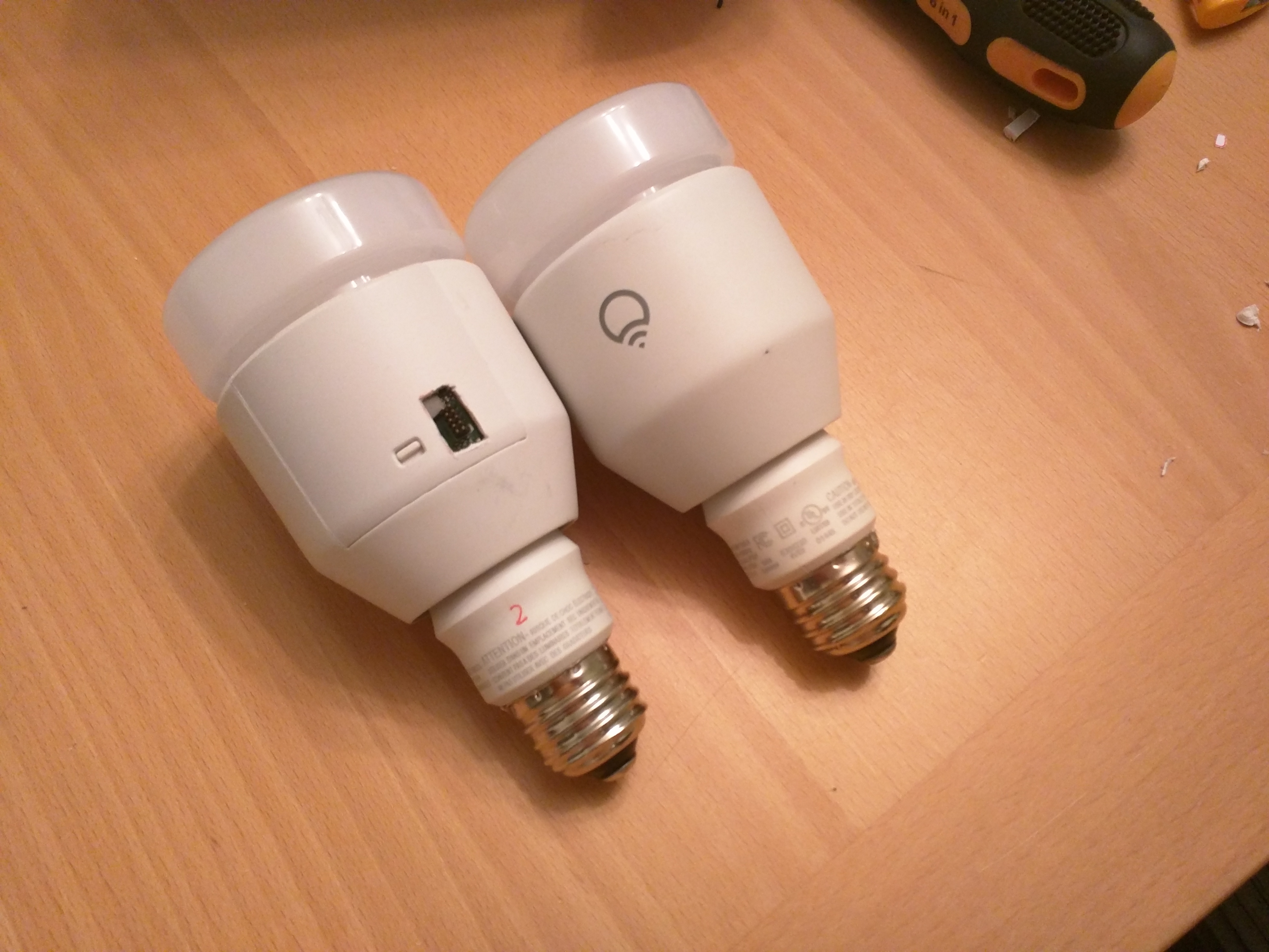
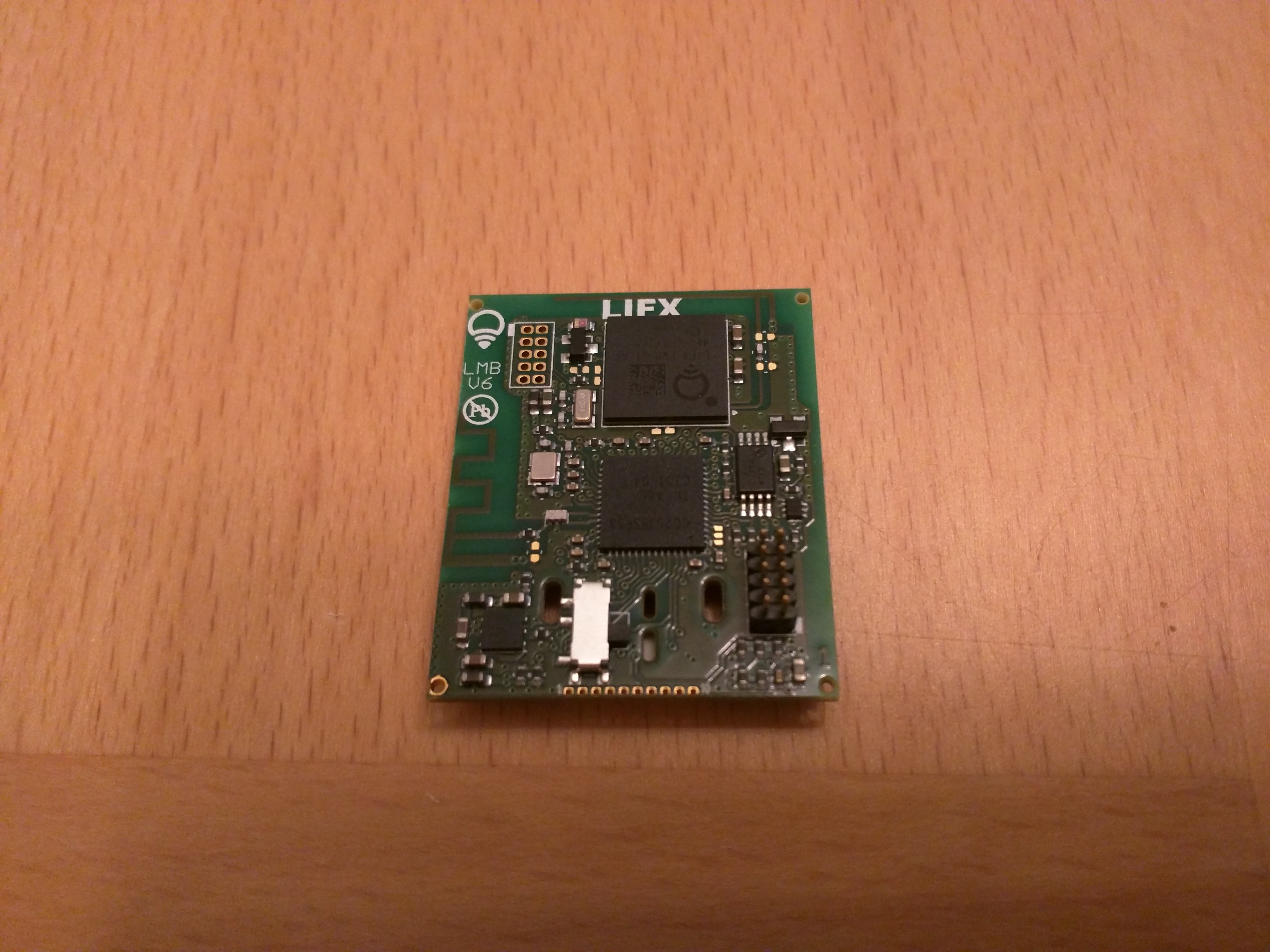
We have chosen the $80 LIFX multicolored LED smart bulb. It has two ARM Cortex-M3 processors onboard to handle WiFI and 802.15.4 radios. What makes this bulb more appropriate than the “CREE Connected” and “Connected by TCP” bulbs is the fact that the onboard LED driver circuit is capable of driving PWM from the processors straight to the LEDs. This allows us to send our light frequency modulated data. The CREE and TCP bubs use a continuous current LED driver circuit that cannot be used without hardware modifications.Software
The software is mostly going to be done on the iOS platform, using the Apple® Cocoa™ Touch library and OpenCV.Protocols
We plan to use our own primitive protocol on top of the 802.15.4 to communicate between a base station and the light bulbs in order to update them without having to re-flash them. As a reach goal, we would like to tap into the WiFi capabilities of the bulb to eliminate the need for a base station.Use Cases
- Exhibit dependent museum lighting for easy companion app to supply information
- Indoor location and navigation, without reliance on imprecise GPS
- Location sensitive security (point phone at office lamp to log in)
- Location tagging with app to attach data to a location for others to find
- Grocery store navigation, with lights on each aisle
Interaction Diagram
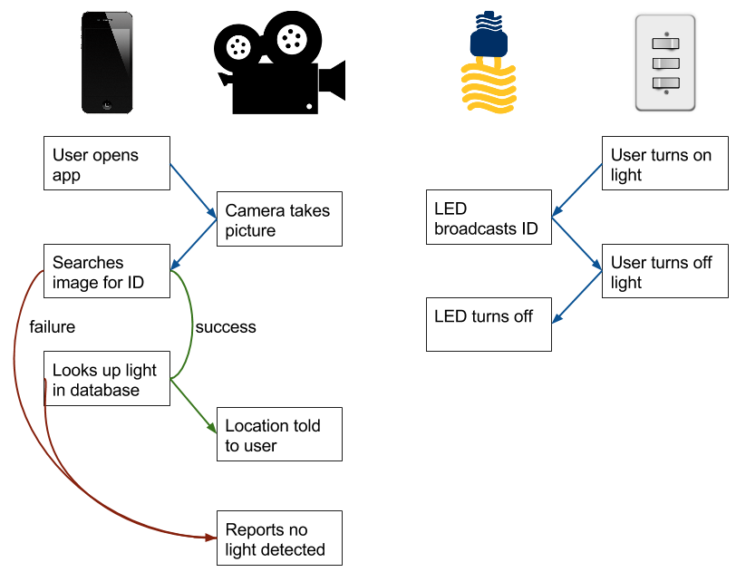
System Architecture

Implementing the Transmitter
The following serves as a tutorial on how to use the LIFX multicolor LED bulb as a VLC transmitter.
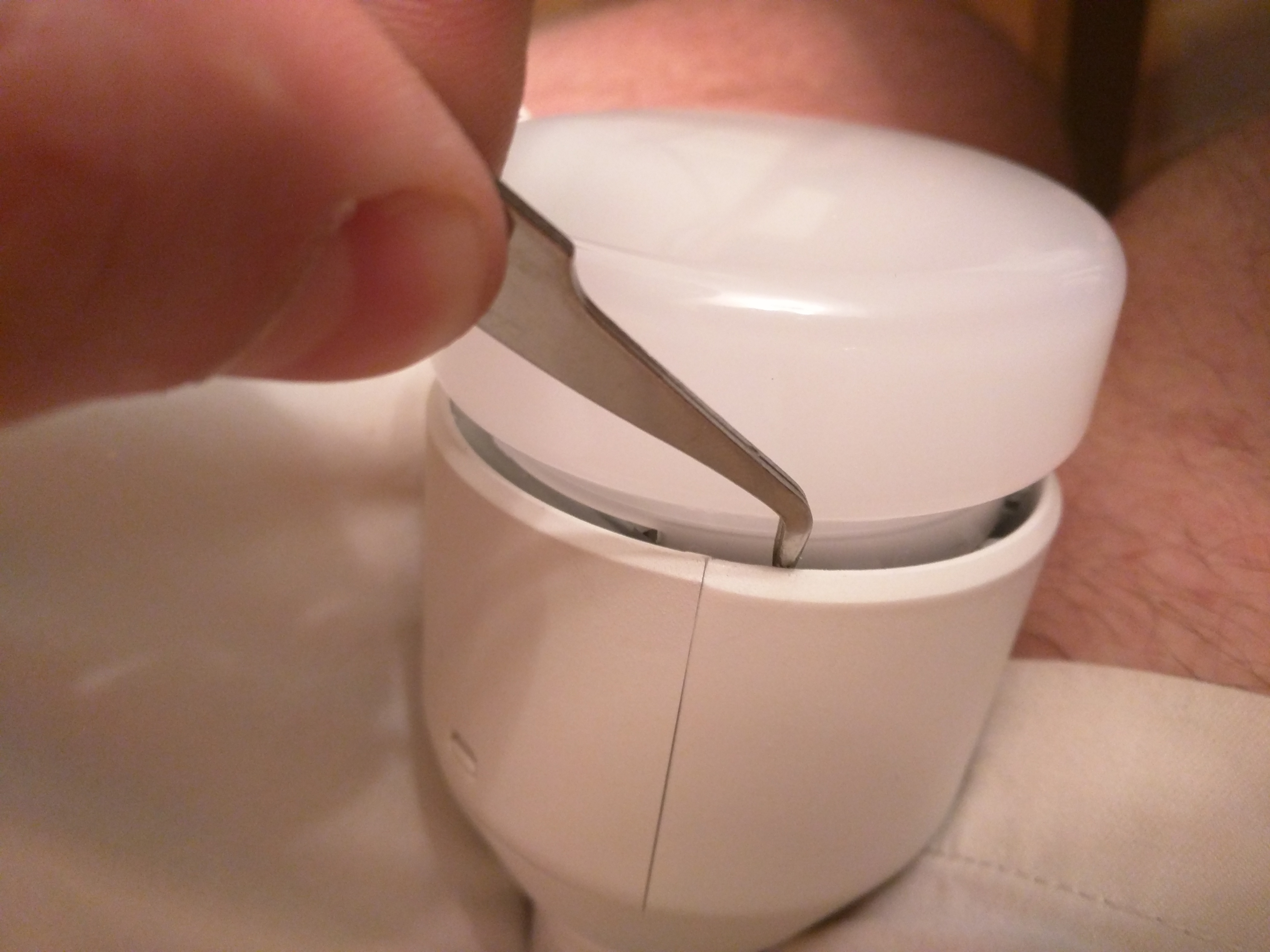
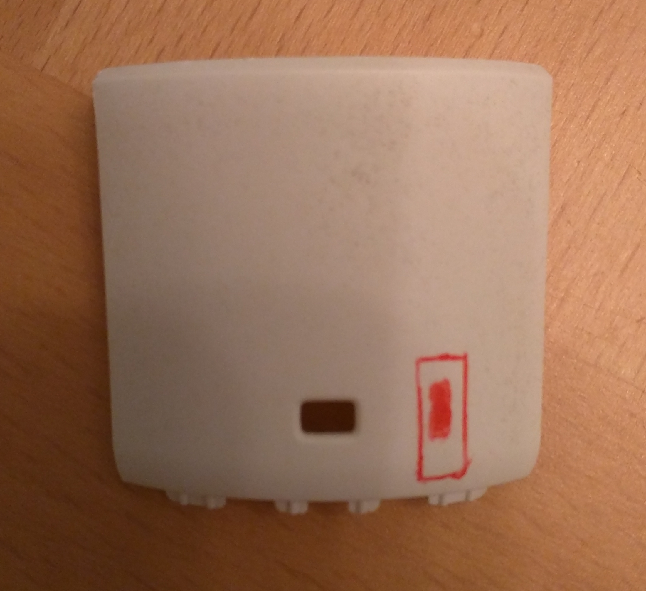
Removing the Lens
The lens must be unlocked by sticking a thin strong piece of metal between the bulb's metal housing and plastic lens, as shown in the figure. The placement is a little less than half an inch to the right of the MCU door. The objective is to depress a small(but sturdy) metal tab that blocks the lens cap from twisting.
While depressing the tab, twist the lens clockwise (looking down on the top of the bulb) about 30 degrees, and then pull off.
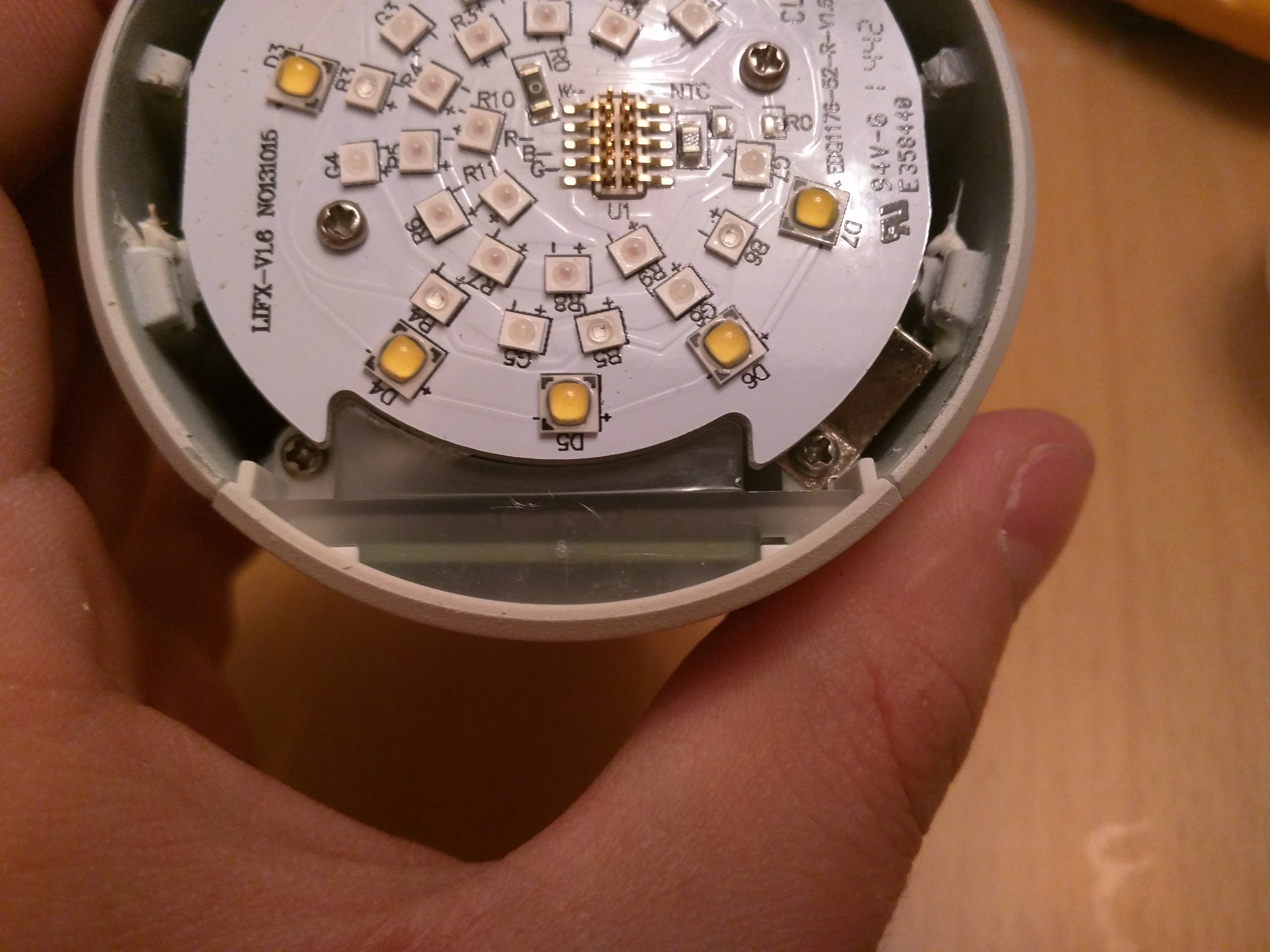
Lens Removed
Here you can see the metal tab on the bottom right that must be depressed. Also, note the two recessed screws towards the bottom of the bulb.
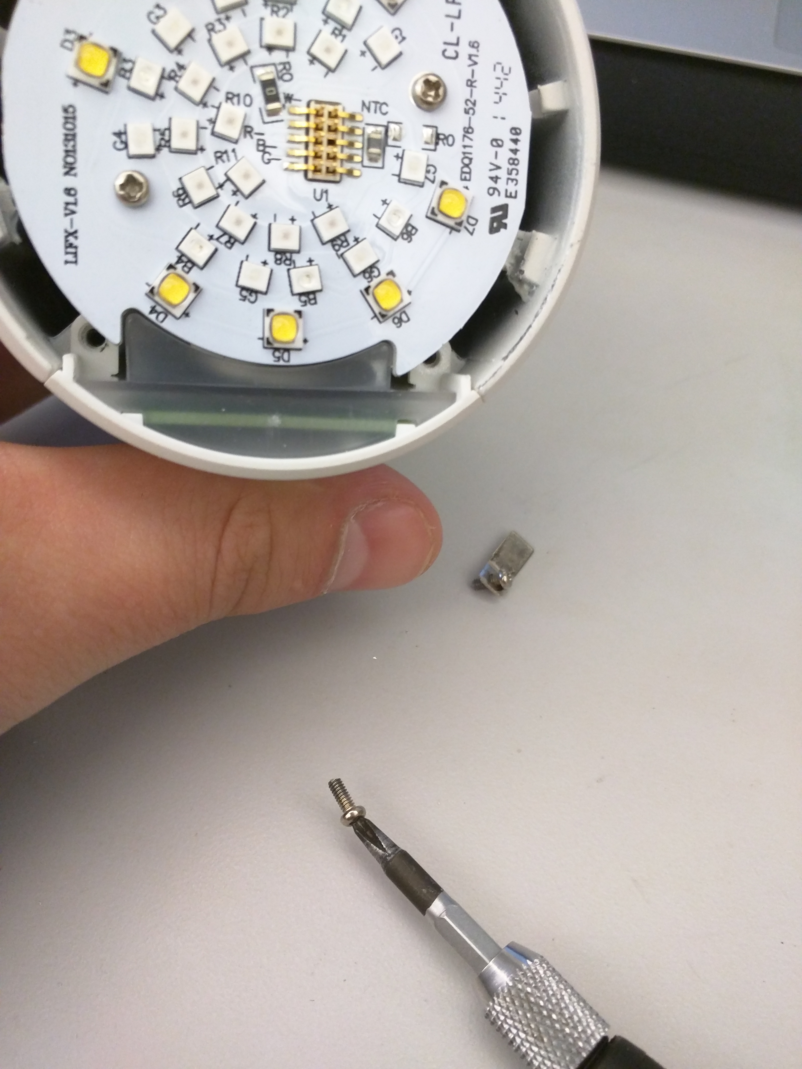
Unscrew MCU Access Door
Unscrew the two screws identified in the last step. The right screw retains the metal tab, which will fall off when the screw is removed.
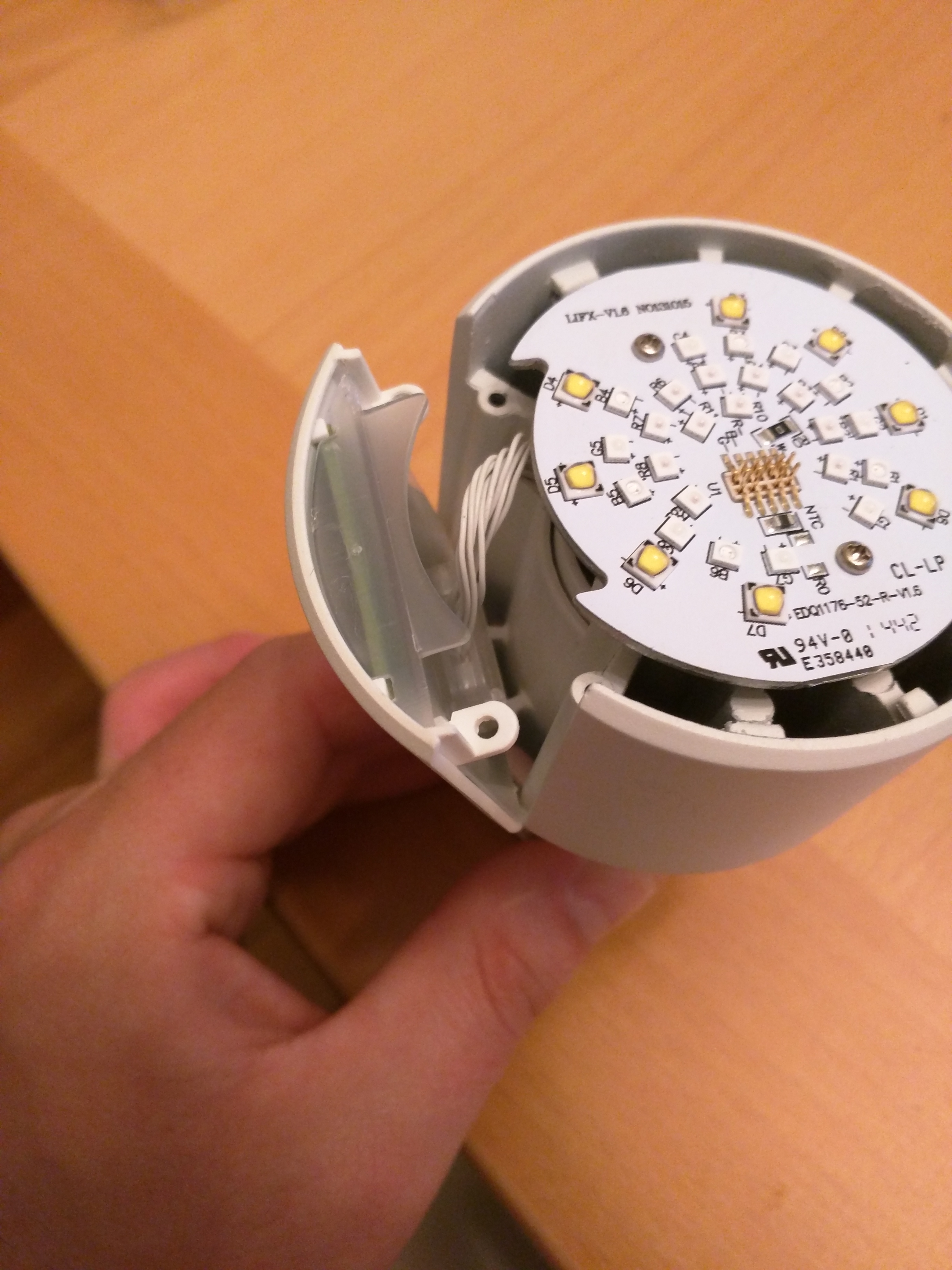
Remove MCU Access Door
Remove the MCU door by pulling the rim of the door outward, away from the bulb housing.
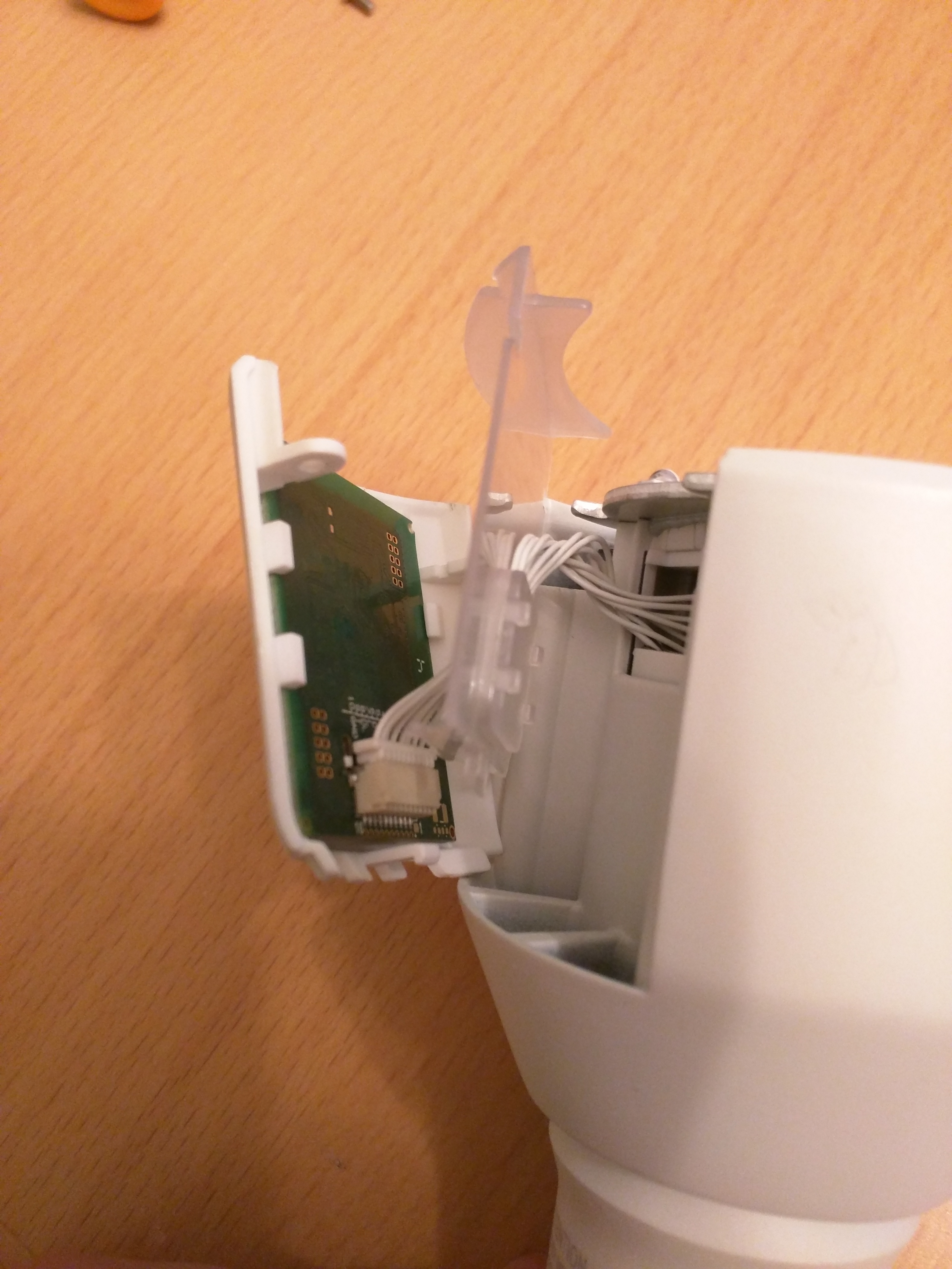
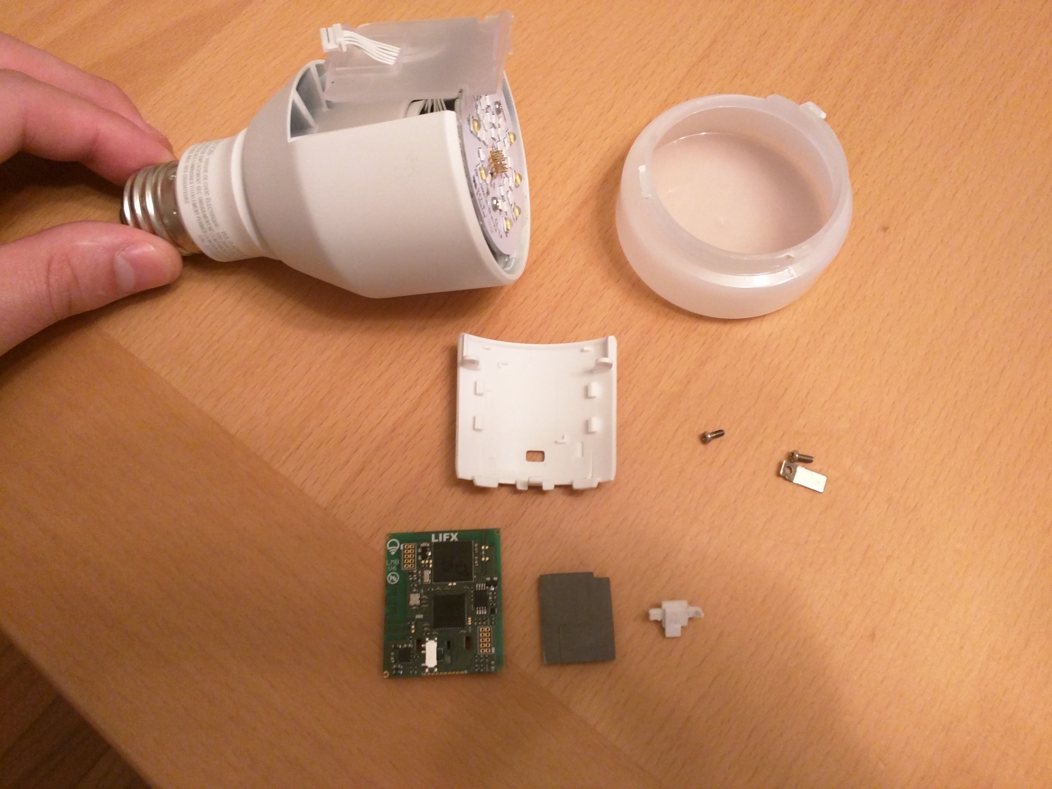
MCU Board Separation
Carefully pry the translucent plastic inside cover away from the white MCU door. Be careful not to strain the wire connector inside.
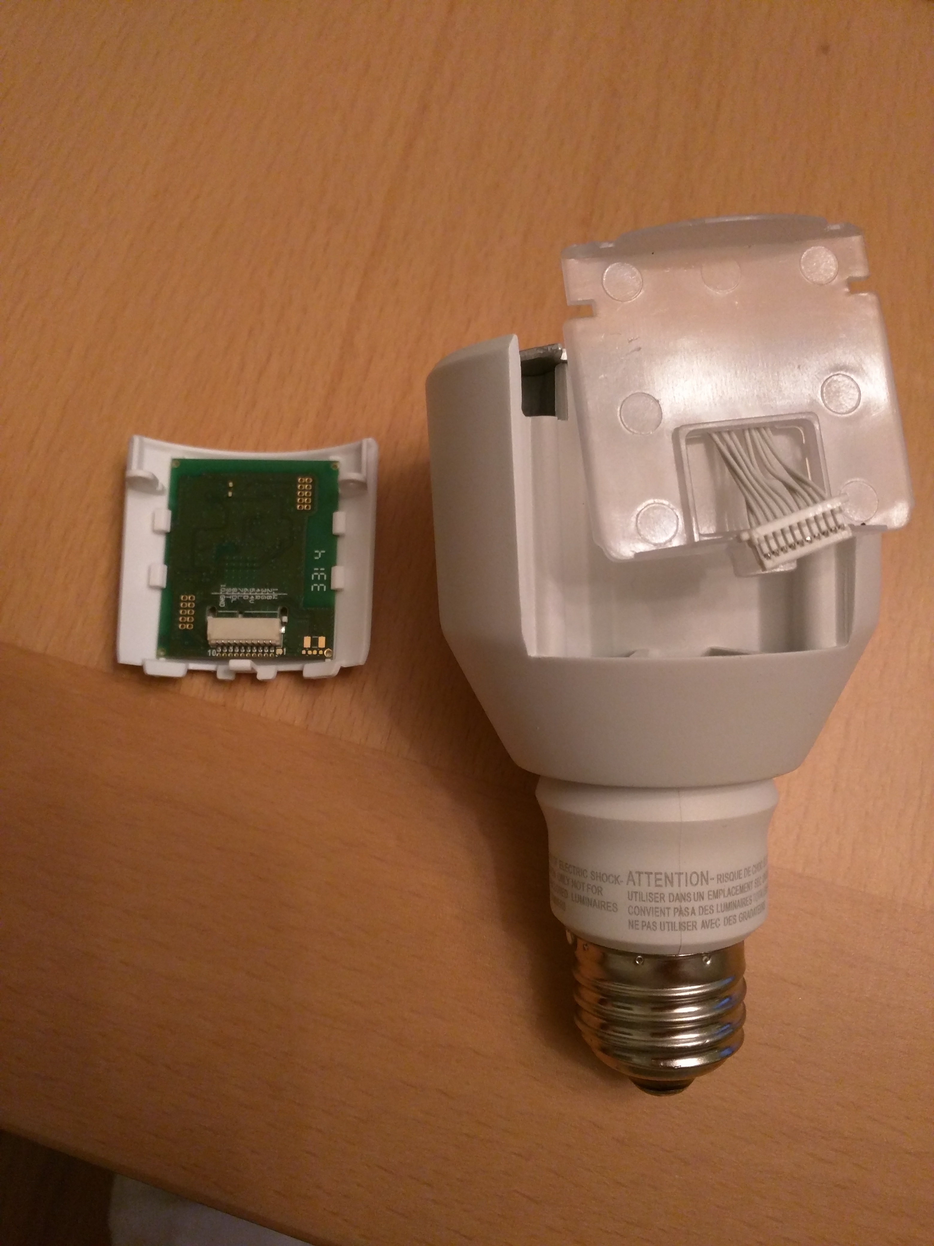
Disconnect Wire Connector
Carefully*
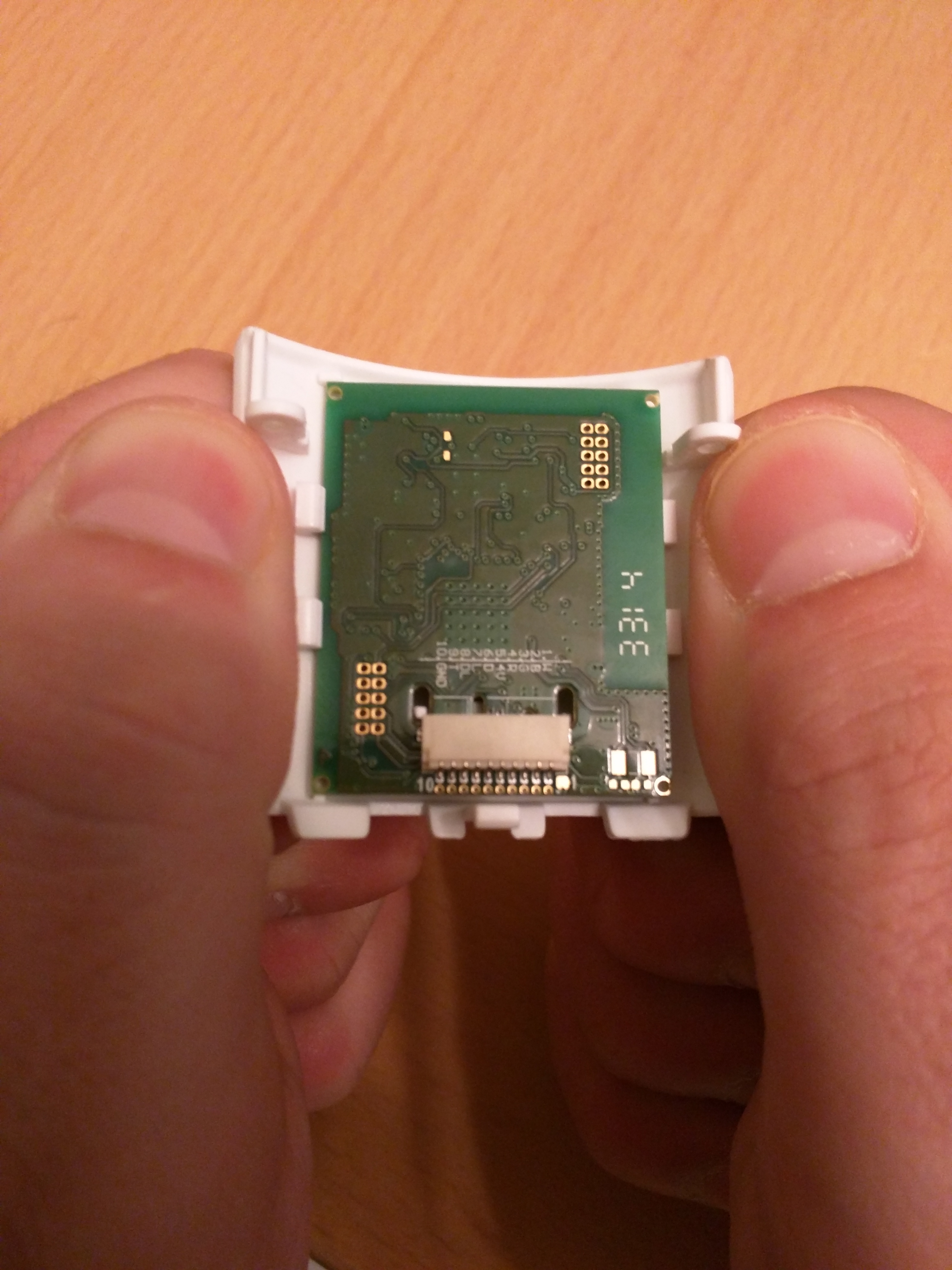
Separate MCU Board From Door
Using your two thumbs, as demonstrated in the figure, pop the MCU board from the white MCU door.
Solder Programming Header
Solder a 10 pin 0.005 inch pitch header onto the MCU board as shown above.
We used the Newark part number 82R7568.
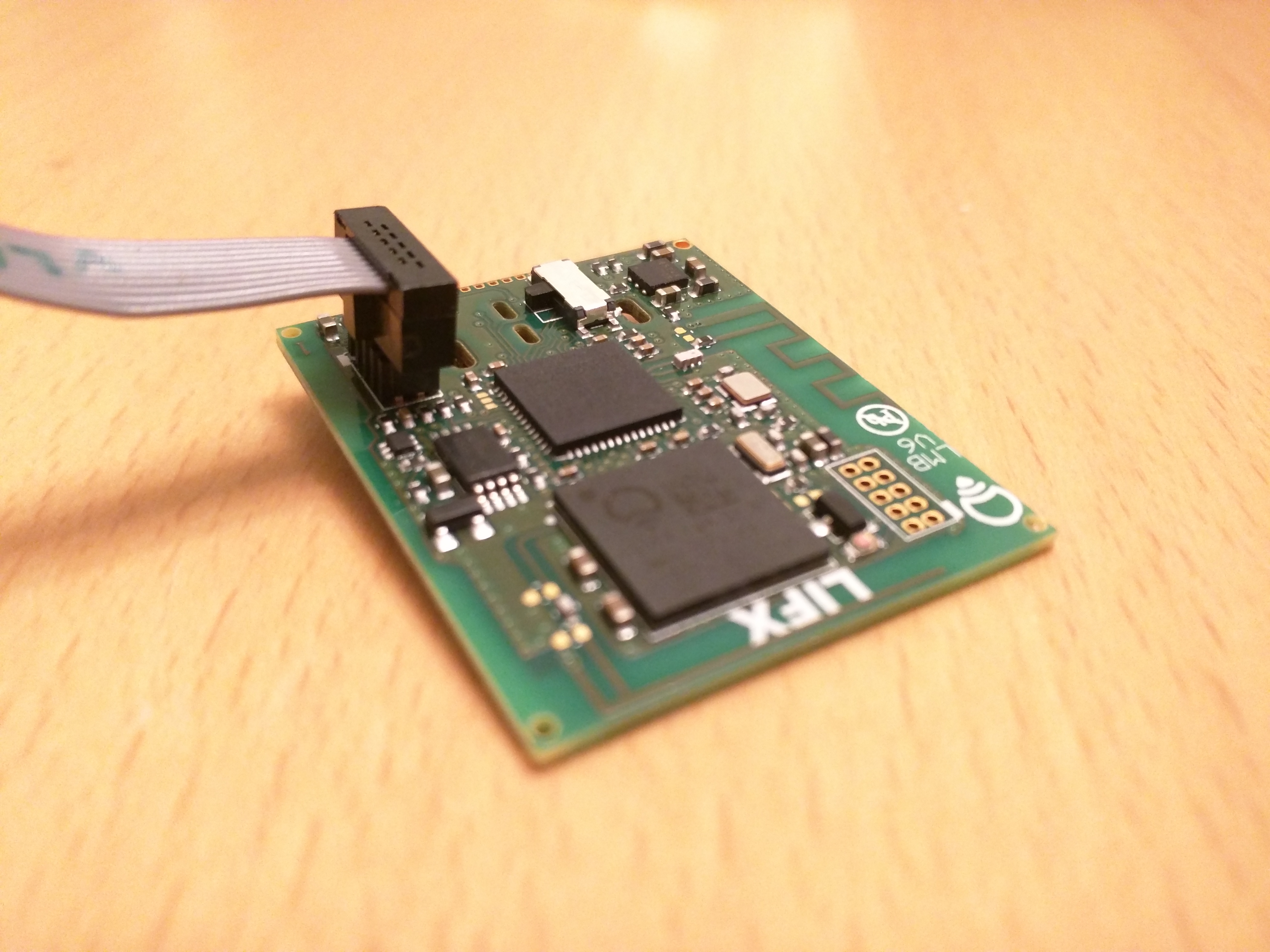
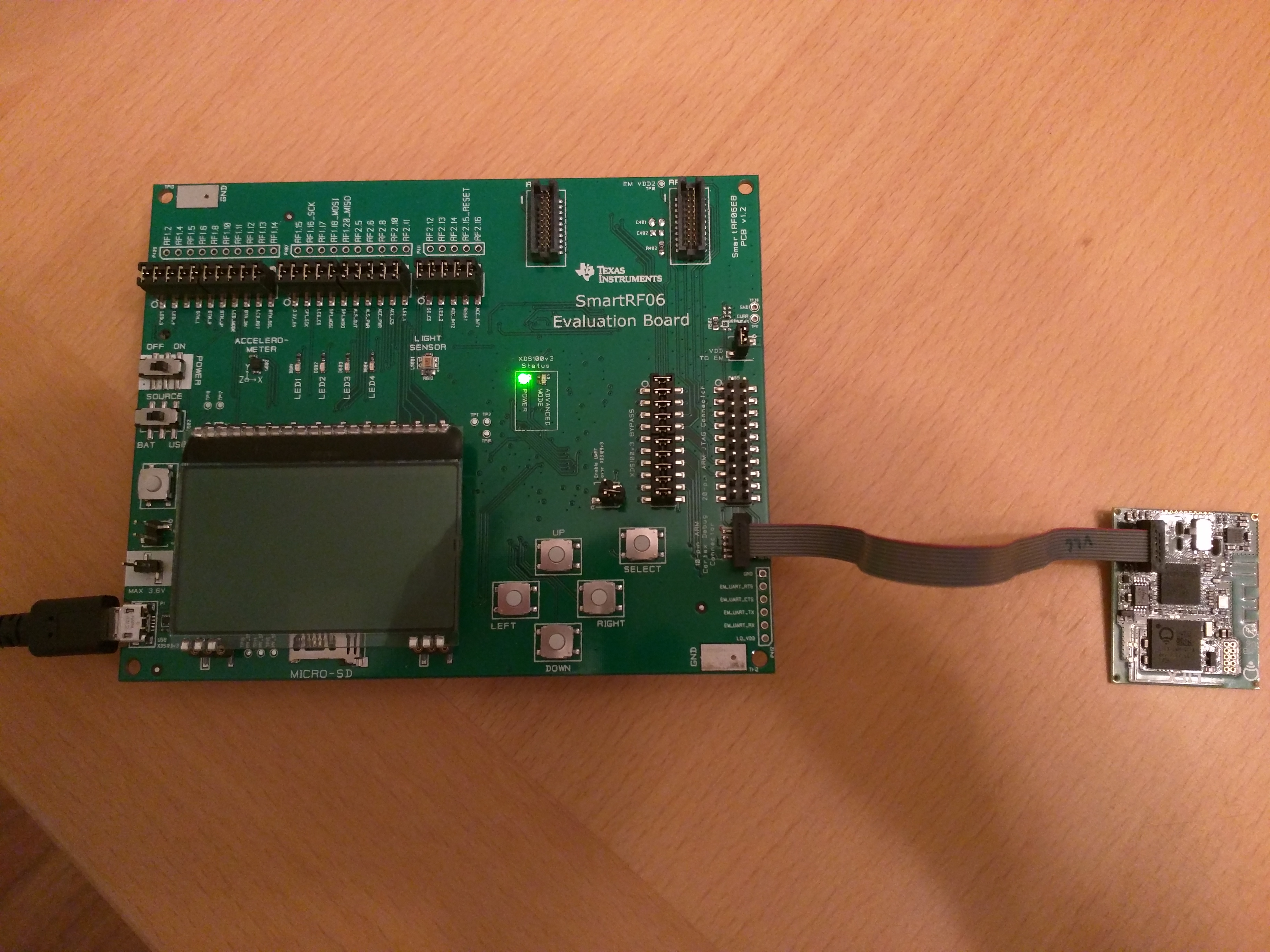
Plug in Cortex Debug Cable
Note the center bump on the connector faces outward. A white bump printed on the PCB indicates this direction.
Plug in Cortex Debug Cable
Note the center bump on the connector faces inward on the programmer.
We used the TI SmartRF06 Evaluation Board for programming and debugging.

Program
- Install TI's Code Composer Studio version 6 or later.
- Download project from GitHub.
- Open, build, and program project in Code Composer Studio.
Cut and Reassemble (optional)
- Cut a small window out of the plastic MCU door to make room for the programming header.
- Reassemble the bulb.
Additional LIFX Notes
-
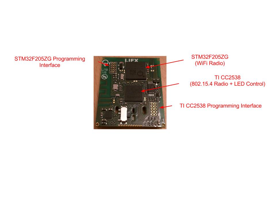
The chip that we reprogrammed was the TI CC2538SF53. It is an ARM Cortex-M3 with an integrated 802.15.4 compliant radio.
It is directly connected to the LED and physical switch control wires.
The files lifx_bulb.h and lifx_bulb.c in the LIFX bulb firmware avaliable on GitHub contain routines for using the switch and the LEDs. -
The other custom chip is said to be a STMicroelectronics STM32F205ZG that is labeled LIFX LWM-01-A. (See Alex Chapman's post here)
It is an ARM Cortex-M3 with an integrated WIFI compliant radio.
We did not try to reprogram this chip, but online research seems to suggest that it runs Contiki.