March 30, 2015
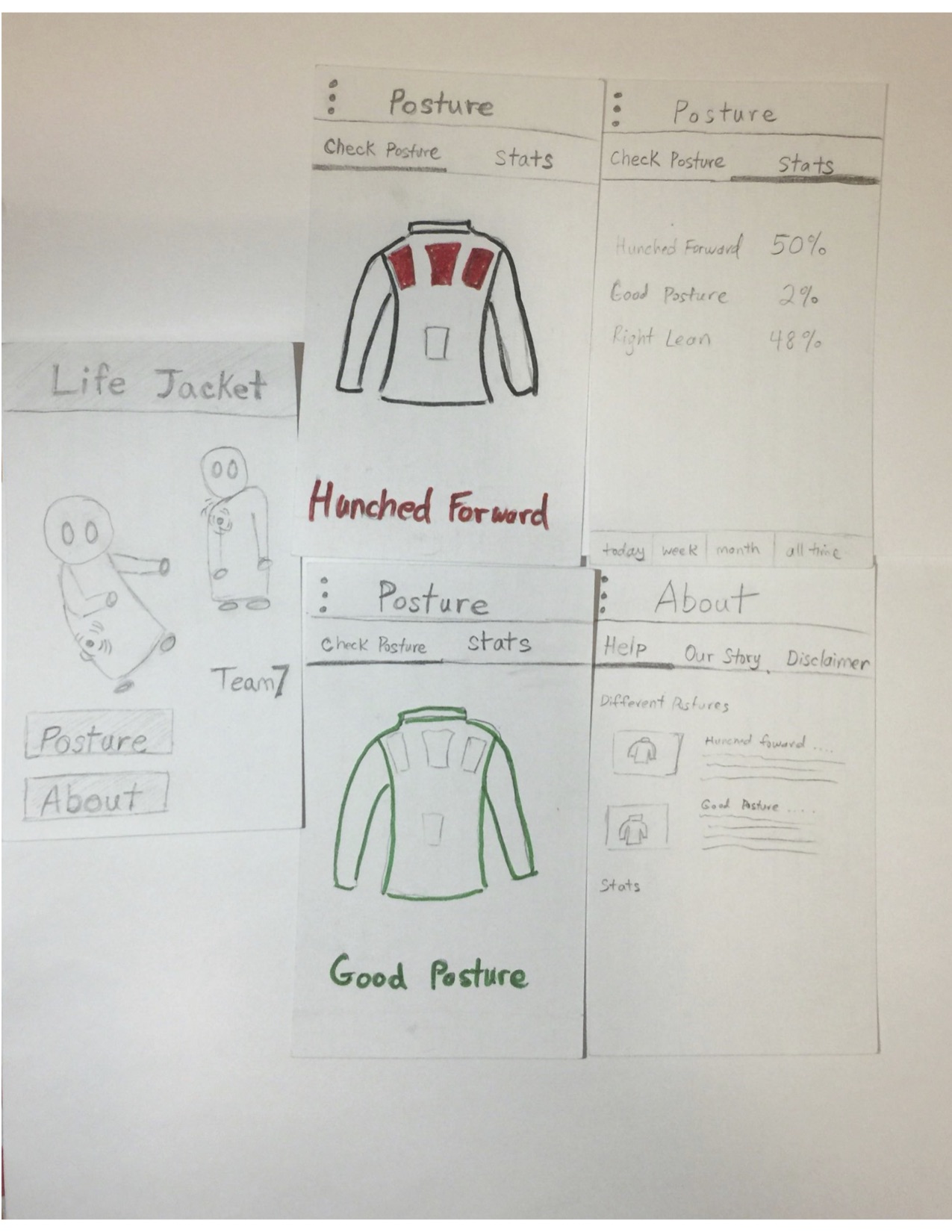
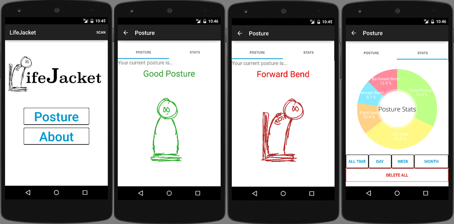
Android Application
App can store fake data from testing input buttons on a fragment of the application. Application can also query and display most current posture. Can search for bluetooth device and read device name but cannot connect and receive data from custom bluetooth module yet.
Bluetooth
Bluetooth USB adapter is able to scan for devices and connect to other devices. We had trouble initiating the pairing from a different device such as a laptop, but seem to be successful with connecting from an Android phone. Since this will be our intended device, this configuration should work for our project.
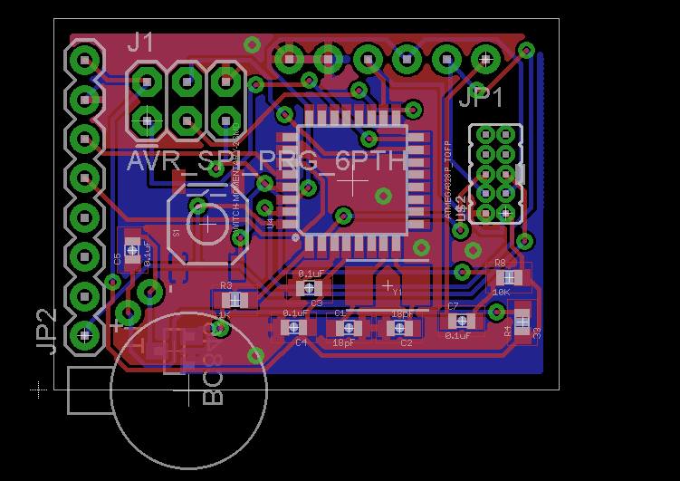
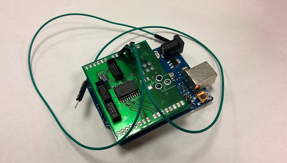
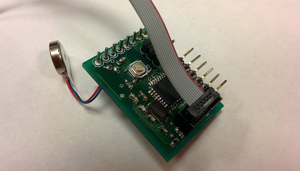
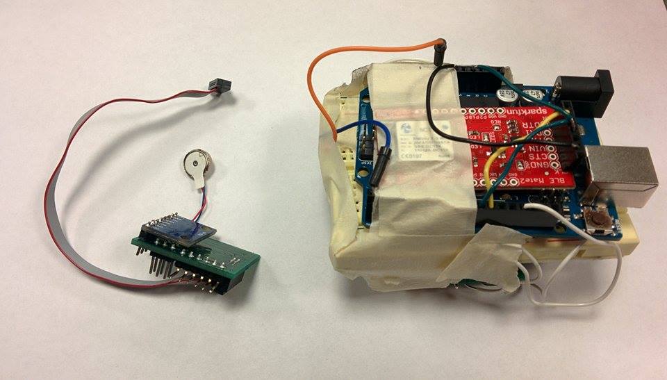
Custom Hardware
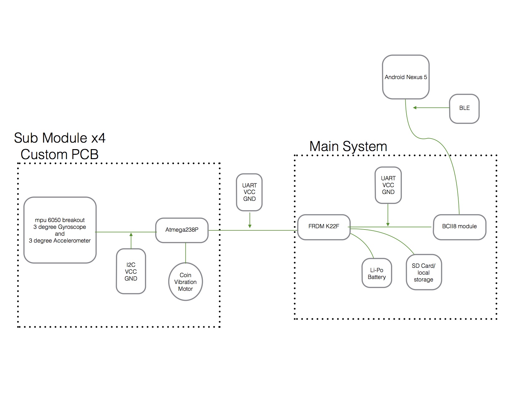
Our sub-module design previously used a separate chip for the gyroscope and accelerometer. We found the Invensense MPU6050 sensor chip which conveniently combines both functions. We incorporated the chip into our PCB design, but we later realized that the MPU6050 SMD chip was tiny and extremely difficult to hand solder. Thus, we decided to use a breakout board instead, which we will solder on to the custom PCB sub-module.
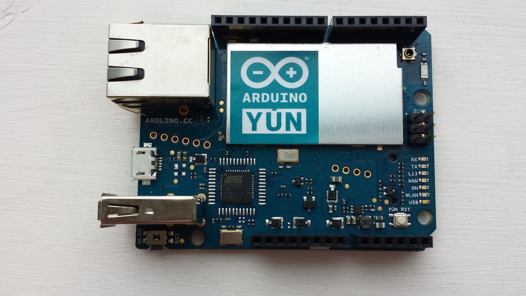
Main Board Decisions
After some testing, the beagle bone black was feasible for our project's scope but soon after working on it, we ran into a large issue. The BBB, due to running a full Linux kernel, had a much larger power consumption and on our current battery would last only an hour or two at most. Started looking for alternative hardware. Ordered the Auduino Yun and FRDM K22F boards.
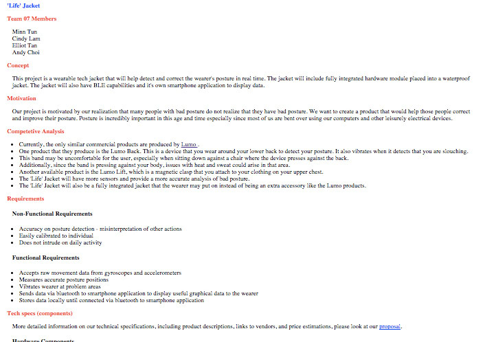
Project Website
The newest version of the project website (currently viewed version) was created. The design of the website was overhauled by using CSS frameworks, and more details and diagrams of the project were added. Also, new pages and links were provided to host future documents and project logs.
Sensors
Since both gyro and accelerometer sensor values could now be dealt by one single microprocessor, the next job was to feed them to a process coded with a higher language so that the data could be processed. Python was initially selected due to the amount of libraries that could support serial communication and machine learning.
Machine Learning Algorithm
Machine learning alogrithms were implemented by using logistic regression. The main libraries used for implementing this were scikit-learn, pandas, scipy, and numpy. The software would intially collect data from the sensors for a specific label provided by the user. After data for a few different states, such as leaning or standing straight, are collected, the user could initiate the training process and have the alogrithm predict a state for newly fed data. This process would later serve as the foundation for the process where the user has a button for calibrating the jacket.