The Video
The Concept

What is (De)Buggy Board?

Step 1: Plan Step 2: Connect Step 3: Debug

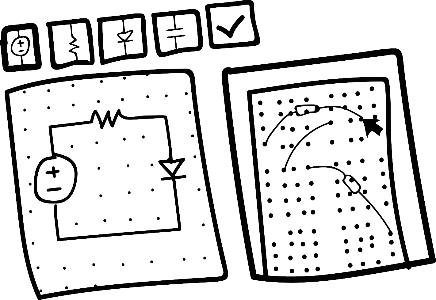
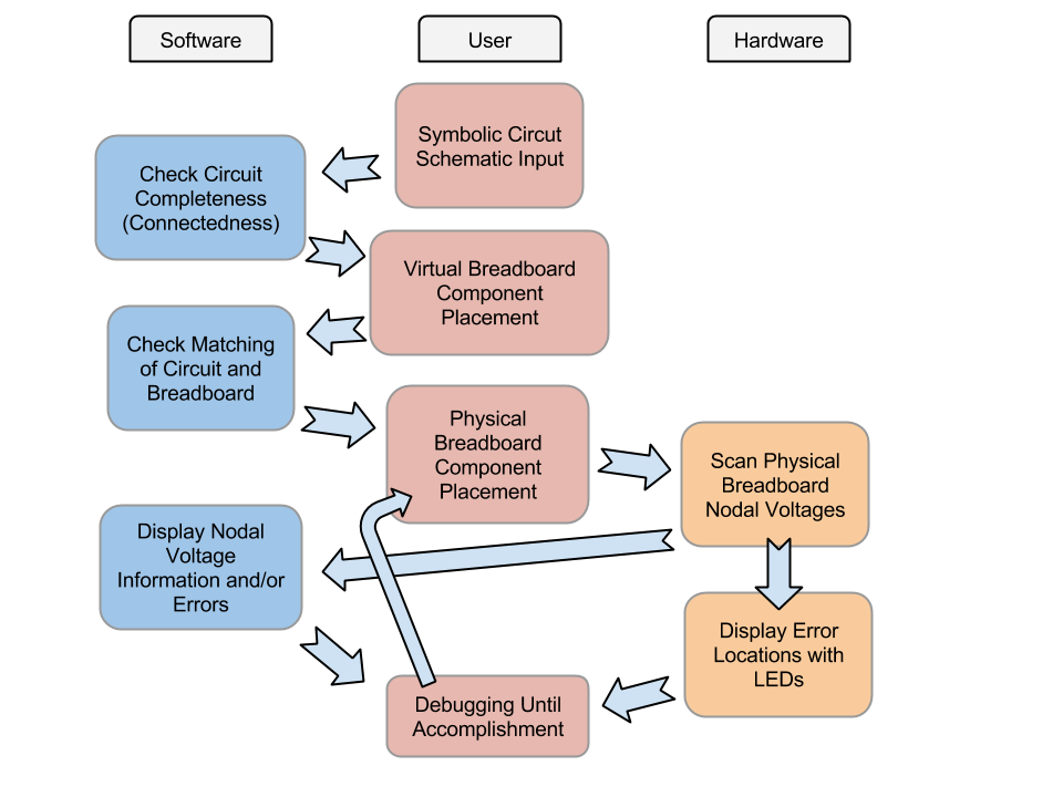
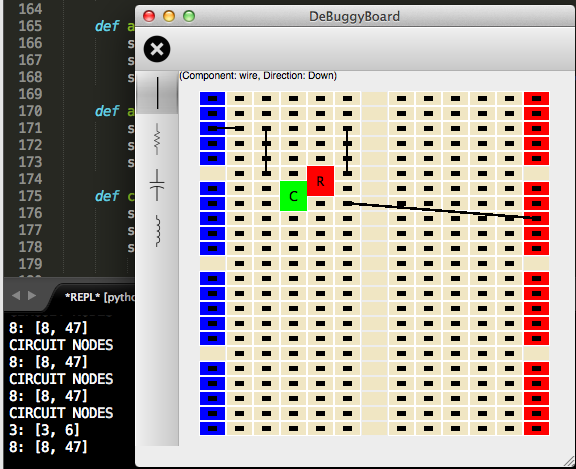
Plan       >       Connect       >       Debug

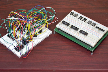
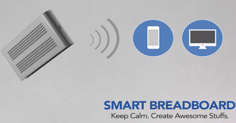
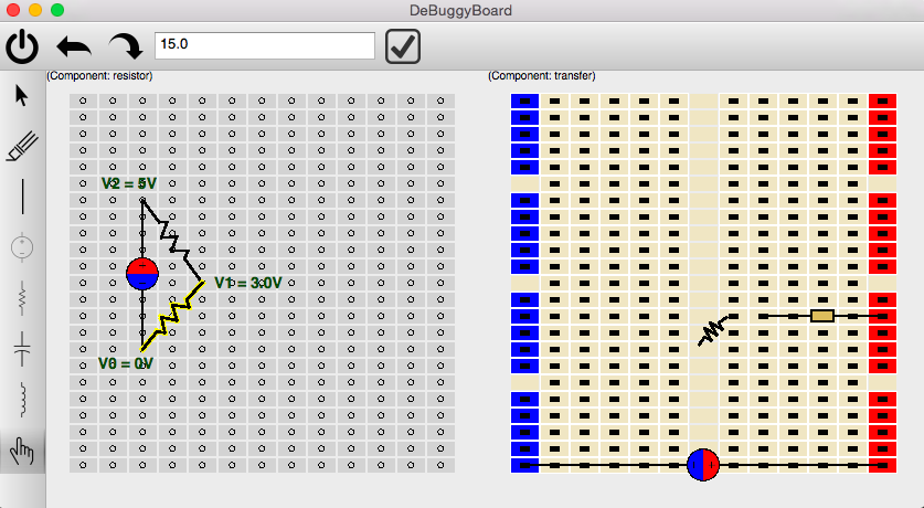
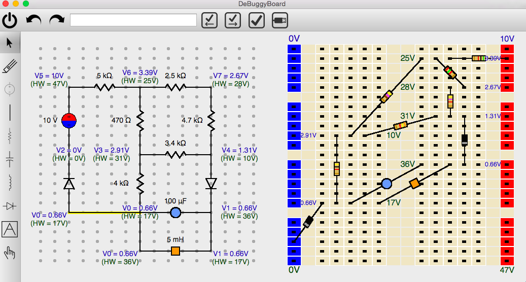
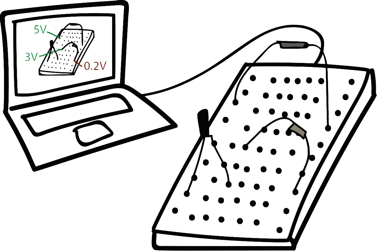
An interactive, educational breadboard to ease circuit-building and debugging.

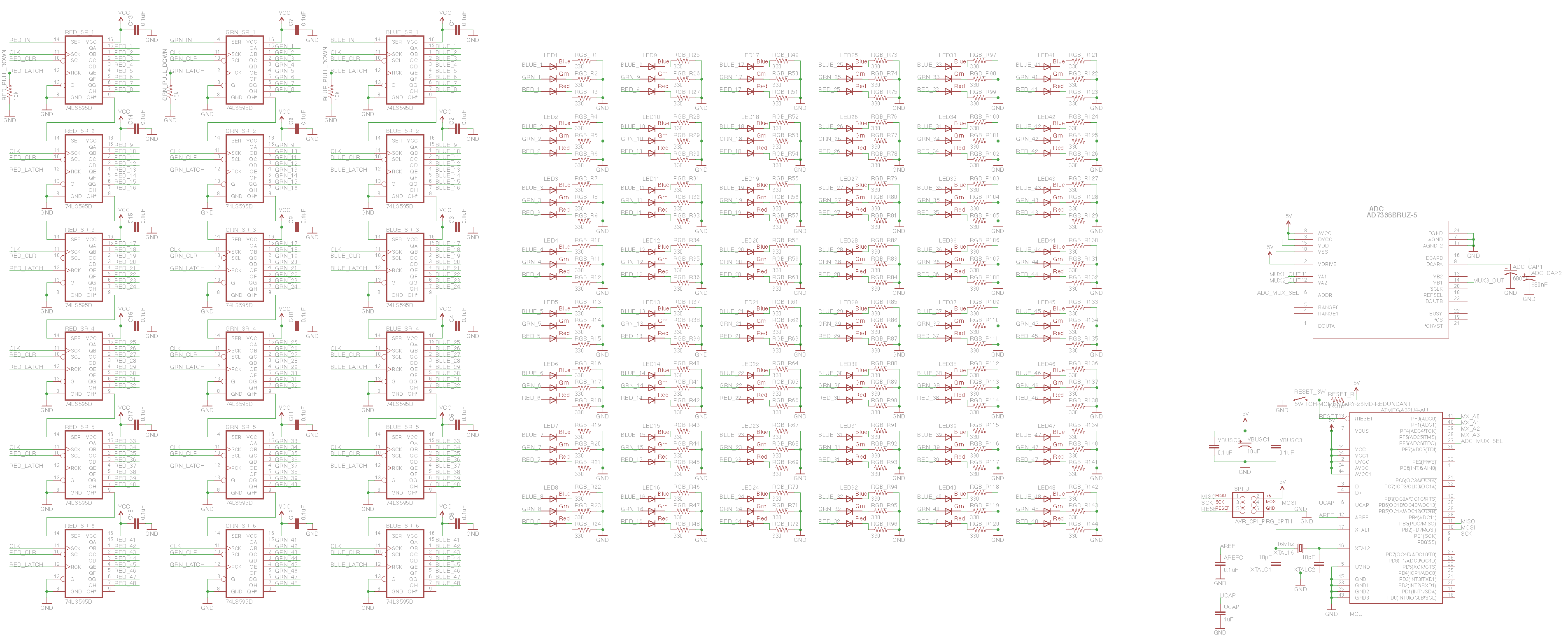
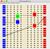
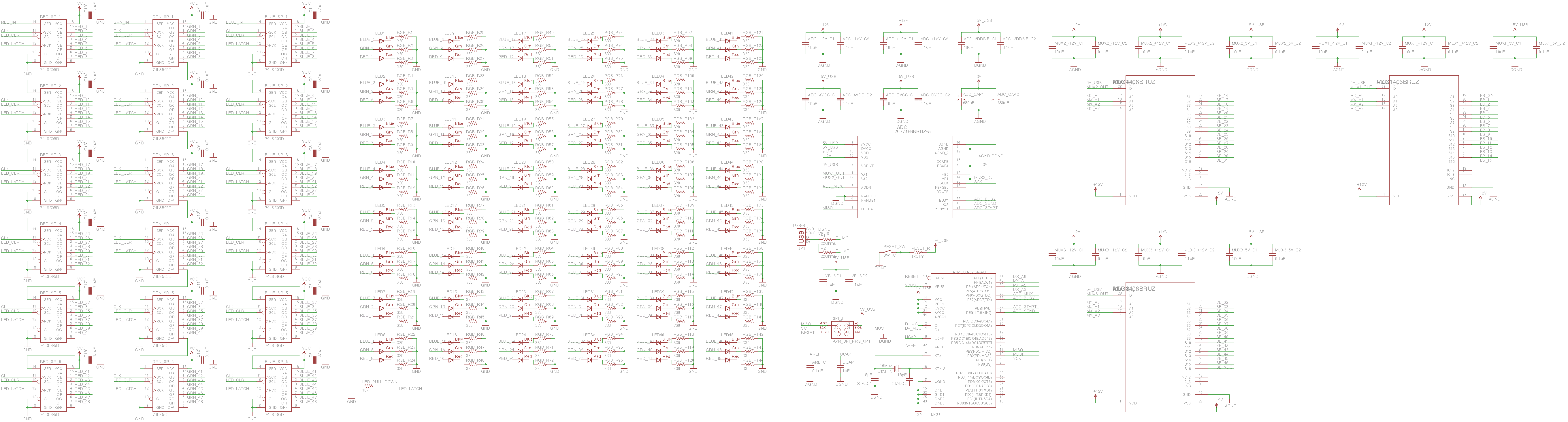
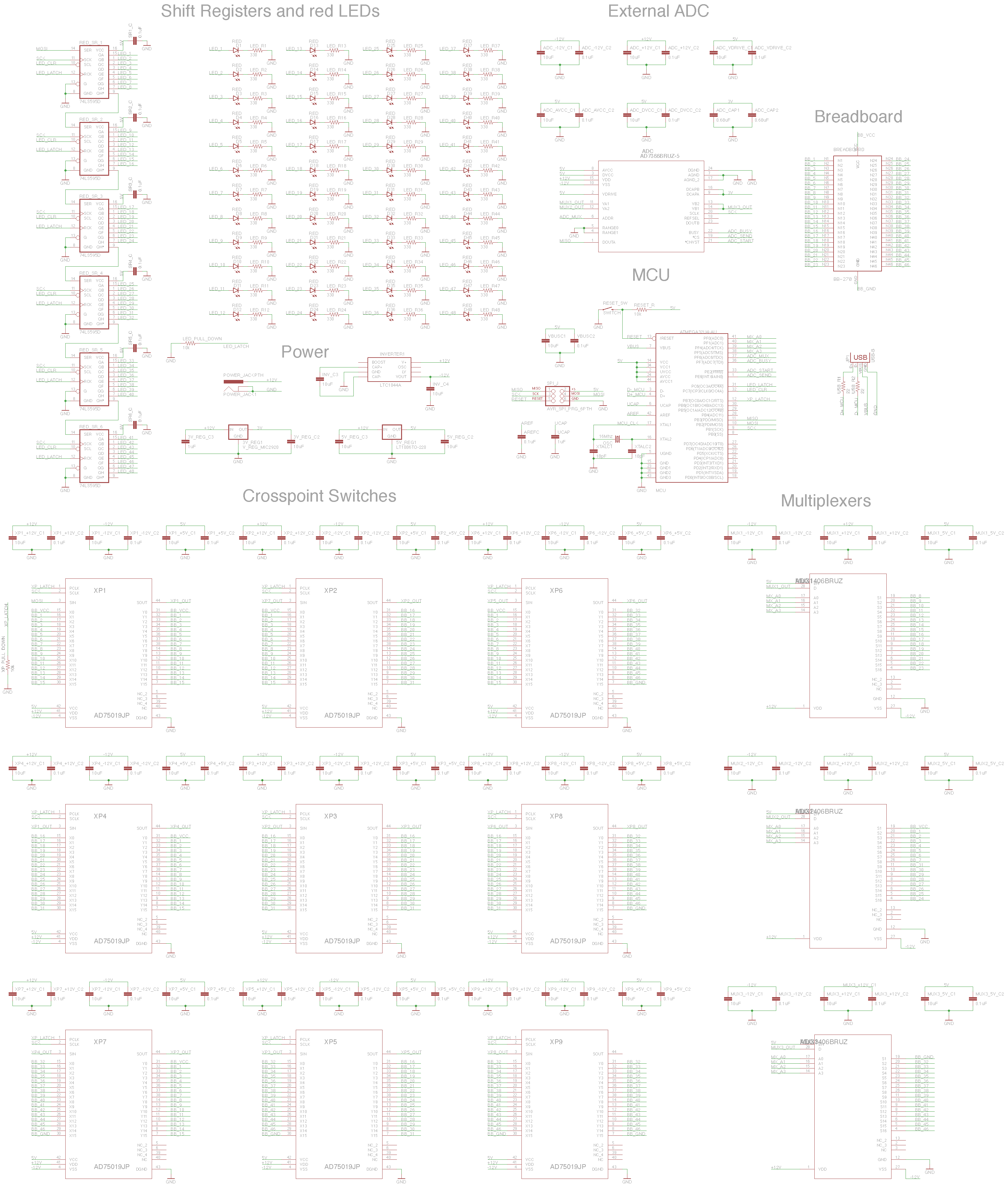
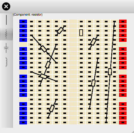
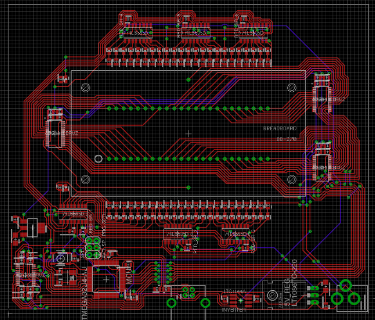
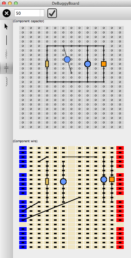
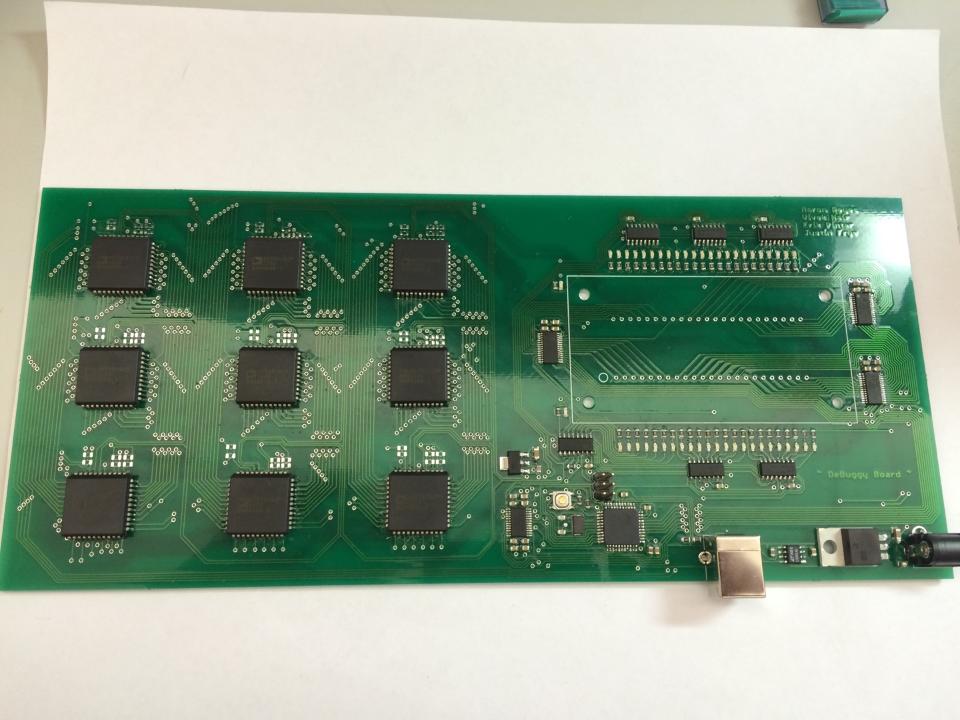
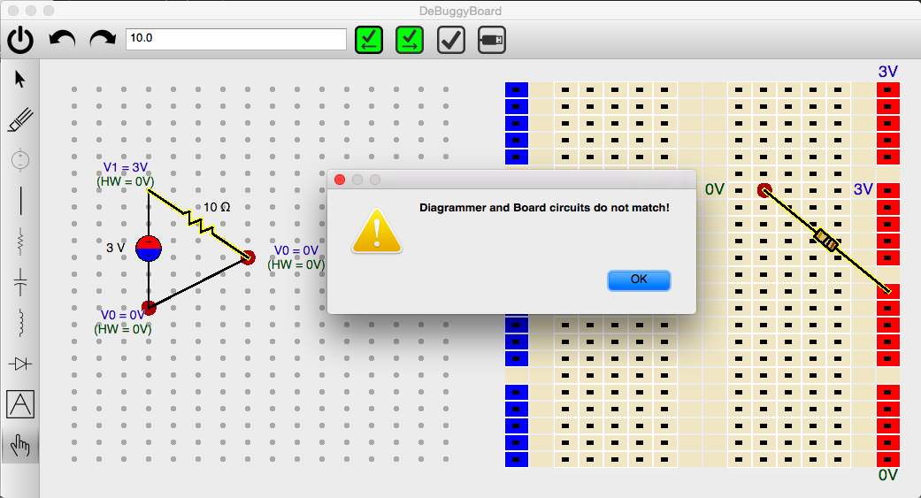
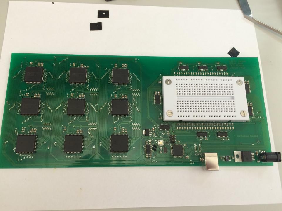
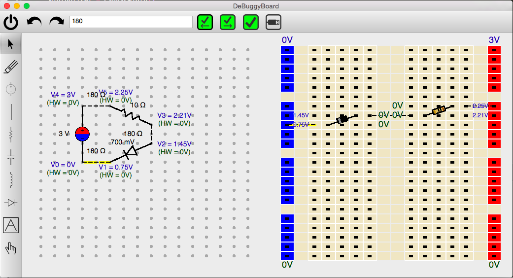
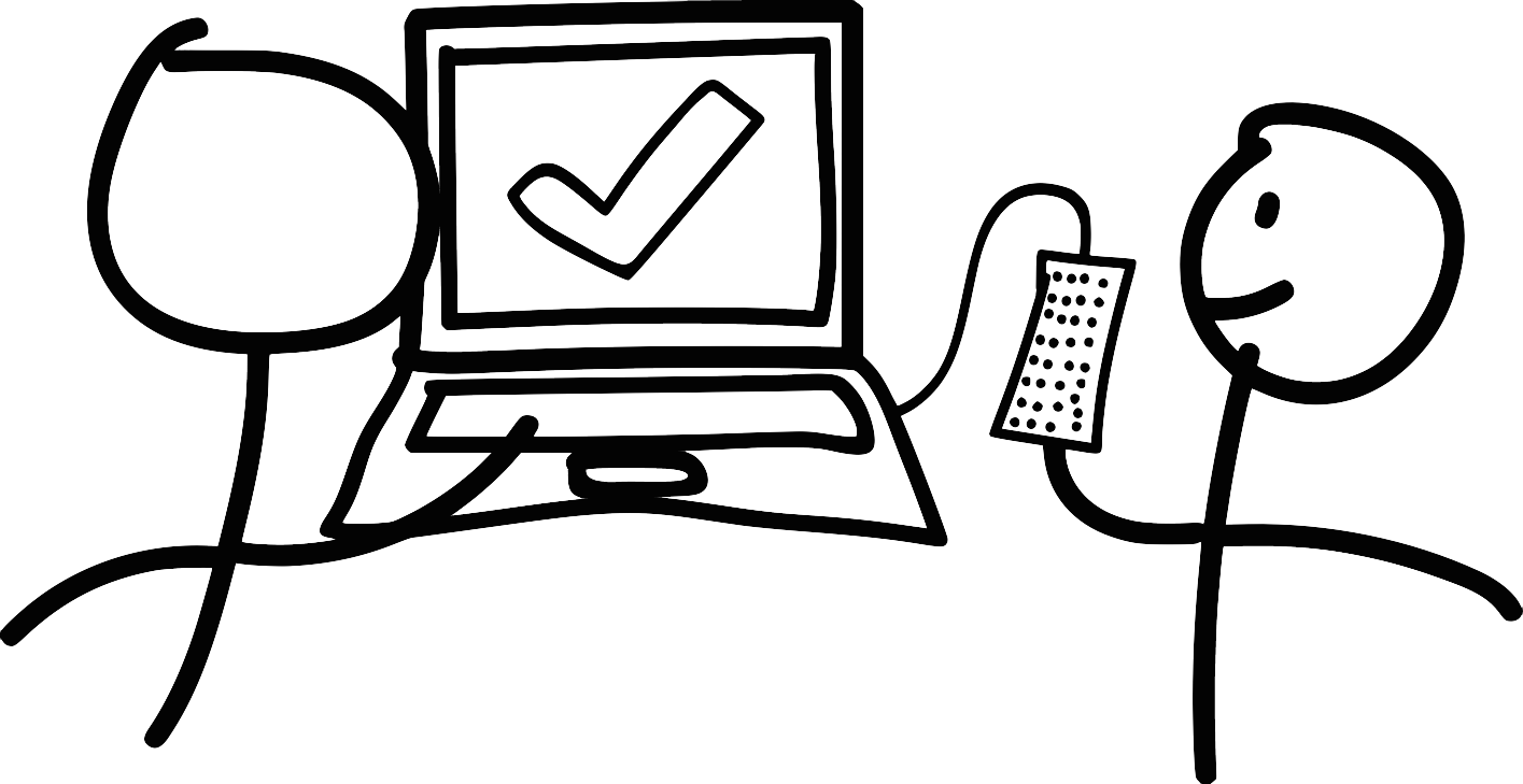
(De)Buggy Board is an interactive, educational breadboard comprising of hardware and software components. Students design the circuit they want to build on a software user interface. Then, as they build it on the breadboard, their circuit design will sync with the software to provide real-time information about their circuit.

The Motivation

The future of introductory circuits education.

This is (De)Buggy Board.

With traditional breadboards, designs can quickly become a dense forest of wires. This requires tedious testing strategies that offer little educational value and tend to be time consuming.

With the (De)Buggy Board, the student will be able to see what voltages are at each node to quickly notice when something simple goes awry. This allows the student to quickly prototype the circuit and get started with the lab at hand.

The Team

Meet the JK Flip Flops.

Aaron Reyes

Hardware Warrior

Personal Site

Vivek Nair

Systems Guru

Personal Site

Erik Pintar

UI Artisan

Personal Site

Justin Frye

Software Samurai

Personal Site
The Requirements

Hardware

Functional


Nodal Voltages

Measure all DC nodal voltages on breadboard and relay voltage data to software.

Auto-Routing

Automatically connect pin rows on the breadboard without wires.

Status LED's

Indicate the status of each pin row on the breadboard via an LED.

Software

Functional


Circuit Diagramming

Provide a user interface for symbolically diagramming circuits. Automatically perform basic error checks on the circuit diagram via KCL and KVL.

Placing and Wiring Components

Create an interface for placing and wiring circuit components from the circuit diagram on on virtual breadboard.

Debugging Feedback

Provide real-time debugging feedback derived from nodal voltages. Is my resistor disconnected? Did I place the capacitor in the correct pins?

Auto-Routing Circuit Visual

Allow for the user to see how their circuit is changed when using auto-routing due to internal resistance of routing fabric (See Components).

Non-Functional


Safety

The circuit should detect dangerously invalid circuits (such as short circuits and high currents) and avoid unsafe operating conditions by shutting down. As first priority, the circuit should not pose physical harm to users through unsafe operation. Second, the circuit’s safety system should prevent internal damage.

Reliability

We will have reliable and accurate DC nodal voltage readings for students to successfully understand the physical circuit they are prototyping.

The Components

What we need to build this.

A.K.A our parts list.

Crosspoint Switch

Required to make auto-routing possible. The main design choice here was buffered or unbuffered. Buffered has low internal resistance but has amplifiers on the outputs, which means we are "imitating" the user's signals and not routing them. This can cause problems in circuits that use feedback. The unbuffered switch just contains a matrix of analog switches. This means a higher internal resistance (approx 200 ohms), but now we actually route signals instead of recreating them. They are also cheaper!

Analog to Digital Converter

To sense the DC voltages, we need an external ADC. We cannot use the MCU's on-chip ADC since the voltage reference of the MCU's ADC is limited by the max supply voltage of the MCU. Limiting nodal voltage sampling to 0 to 5v is not user-friendly. Therefore, our ADC will have high supply rails (+/- 12v) to give the user more possibilities.

Microcontroller

We need only a simple MCU. We decided to pick one with USB support in order to make our communication protocol with the software application simple. Atmel MCU hack support is fantastic online since the processor is widely used in arduino chips. This MCU is responsible for receiving commands from the application to control the LEDs, the crosspoint switches, and track nodal voltages.

Analog Mux

Used to multiplex in all the breadboard nodes to the external ADC for DC voltage sampling. These muxes also need to have the high supply rails of our ADC (+/- 12v) in order to allow for the signals to pass through correctly.

Shift Registers

Used to minimize IO from the MCU used to control the LEDS along the breadboard. Nothing crazy here. Just some simple 8 bit shift registers. We need 6 ICs per a given color to control a 48 node breadboard with an LED for each node. Therefore, we need 18 total ICs.

Small Breadboard

The all-important breadboard. Due to our budget, we can only afford a 48 node board. We achieve this by daisy chaining crosspoint switches. Using a 16x16 switch, we need a grid of 9 switches total to have 48 unique nodes. These 9 switches will exhaust the majority of our budget.

Competitive Analysis

Egyptian Team

An eight-person team from Egypt designed an auto routing breadboard that uses a software backend to route nodes. Their design and goals are similar to ours, but lack the real-time voltage tracking that is essential for our debugging application.

Learn More

No Wires Breadboard

This the only product similar to our concept that we could find. It has features similar to ours, such as an attached software to plan your breadboard wiring, and LEDs to guide placement. As it turns out, this product is actually made by the Egyptian Team. This product is currently not for sale as it is still in development.

Learn More

Build18 Projects

There have been two similar projects within Carnegie Mellon’s annual Build18 hardware hackathon. The ProtoSmart team created a breadboard that sensed voltages at each row of a small breadboard. The Field Programmable Protoboard team set out to make a breadboard that wires rows together for you (auto-routing).

Learn More

Bisko Smart BreadBoard

This team is still a work in progress, but has a nifty video. They aim to create a breadboard that communicates wirelessly with a computer or your smartphone, which is an interesting feature we are not including. The goal for their product is also very similar to ours: reduce circuit-building frustration!

See Video
Design

System Architecture


Our software system architecture, presented in a diagram of class structures and how they interrelate.

Use Cases


This is what an ideal use case will look like:

  • User inputs symbolic circuit schematic into the circuit diagrammer.
  • User moves components from the schematic to the virtual breadboard.
  • User places the components on the real breadboard.
  • Hardware scans real breadboard nodal voltages and sends the data to the software, displayed as useful debugging information.

Error use cases that could come up are:

  • The symbolic circuit is incomplete (not all components are wired or have values associated with them); software highlights wrong components.
  • The symbolic diagram does not match the breadboard diagram; software highlights which nodes don't match.
  • Theoretical voltages differ from real voltages; rows in the software light up red as well as red LEDs on the physical board!

User-Interaction Diagram


Our user interactions, as a visual representation of the hardware and software systems interacting with the user.

Progress

So what have we done so far?

"If there is no struggle, there is no progress." - Frederick Douglass


16 March 2015

Eagle schematic of LEDs and MCU with peripherals. Working on adding ADC with muxes and then making sure design passes ERC check.
Bare-bone circuit routing GUI. Working on symbolic circuit diagrammer UI and enhancing circuit routing UI.

23 March 2015

Near-complete Eagle schematic for full hardware design without switching matrix. Working on connecting muxes, ADC, and shift registers to MCU to minimize IO usage. After adding power circuit to schematic, we will layout our PCB and make a custom part/footprint for the breadboard to connect to the PCB (hopefully all by next checkpoint).
GUI sidebars, node detection, and basic use of pySPICE. Working on connecting pySPICE to a circuit diagrammer UI and drawing resistors and capacitors as wire objects instead of blocks.

30 March 2015

Completed eagle schematic We will have the PCB layout by next checkpoint with all parts in our parts list ordered. While the board is being fabbed, we will write the firmware and collect our parts. Here is our full parts list.
Circuit solving using Ahkab and symbolic circuit diagrammer design. We can solve basic circuits using Ahkab (Python circuit solving library). We also made UI updates to the circuit router with improved graphics for wires and resistors.

6 April 2015

The routing for the board without crosspoint switches is done. That is being shipped out today. We will then ship out the board with crosspoint switches this Thursday to be fabbed.
Symbolic circuit diagrammer is now shown right above the breadboard diagrammer. Functionality added to add values to components. Also a nice UI improvement of a transparent preview of the component you are currently placing.

13 April 2015

Completed EAGLE routing! The Eagle automatic routing algorithms could not even attempt to achieve this. Board was shipped out 4/9/15.
Ahkab Integration Progress and GUI Improvements. Ahkab runs and attempts to verify the circuit when components are placed on the diagrammer. We added a voltage source component for diagrammer, delete button for circuit components, and undo/redo functionality. Users can select circuit components not only by clicking on their nodes but also by clicking on the actual components.

20 April 2015

Firmware code has been developed. Functionality for sending node voltages, signaling which LEDs to light up, and what wires to auto-route have been written.
Voltage labels and Ahkab board integration. Diagrammer nodes are labeled with their calculated voltages and intelligently positioned. Users can click components on the diagrammer and move them to the board making synced components. Diagrammer resistors are now the squiggly kind we know and love.

27 April 2015

Soldered components onto board - Whew! The MCU and LEDs are operational now. With minor exceptions, all components are soldered to the board, and we are ready for full board bringup.
Comparing Diagrammer and Board Circuits in Ahkab. The intended user flow is functionally complete. Users can make a circuit with the diagrammer, transfer its components to the Board, check that the two are equal, and begin measuring voltages from hardware.

2 May 2015: Final Demo

(Mostly) Completed Board Bringup. The crosspoint switches (reach goal) are operational; the ADC is working but noisy, causing nodal voltage sampling woes.
Completed Autorouting feature in Software. Dashed lines represent autorouted wires, which users can see in software but do not place on the physical breadboard.

8 May 2015: Public Demo

Nodal Voltage Sampling and Auto-routing Functional. We can measure nodal voltages in real-time using the ADC, and we can auto-route circuits via the crosspoint switches through the software auto-routing feature. Victory.
Updated Diode Model for LEDs and More Robust Circuit Equivalence Checking. We represent the diode as a constant voltage drop as often done in introductory circuits courses. We rewrote the Diagrammer and Board equivalent circuit checker to improve robustness and fix bugs.
The End